To Create a Perimeter Scan

To create a Perimeter scan:

  1. Ensure that you have a laser probe enabled.

  2. Place PC-DMIS into DCC mode.

  3. Select the Insert | Scan | Perimeter menu item. The Scan dialog box appears with Perimeter Scan already selected in the Scan type list.

  4. Select the surface or surfaces to use to create the boundary. If you select multiple surfaces, you should select the surfaces in the same order that they are to be traversed by the scan. To select the necessary surface or surfaces:

  1. Verify that the Select check box is selected. Each surface is highlighted as you select it.

  2. After you select the desired surfaces, clear the Select check box.

  3. Click on the surface near the boundary where the scan is to begin. This is the Start Point.

  4. Click on the same surface a second time in the direction that the scan is to be executed. This is the Direction Point.

  5. Click the point where the scan is to end. This point is optional. If you do not provide an End Point, the scan ends at its Start point.

  1. Type the appropriate values into the Scan parameters area. These include the following boxes:

  1. Select the Calculate Boundary button to calculate the boundary from which to create the scan. The red dots on the boundary indicate where the hits are taken on the perimeter scan.

The boundary calculation should be a relatively quick process.

If the boundary does not look correct, click the Delete button. This deletes the boundary and allows another to be created.

If the boundary appears incorrect, it usually means that you need to increase the CAD tolerance.

After you change the CAD tolerance, click the Calculate Boundary button to recalculate the boundary.

Verify that the boundary is correct before you perform a perimeter scan because it takes much longer to calculate the scan path than it does to recalculate the boundary.

  1. Verify that the Offset value is correct.

  2. Click the Generate button. PC-DMIS calculates the theoretical values used to execute the scan. This process involves a very time intensive algorithm. Depending on the complexity of the selected surfaces and the amount of points that are being calculated, it may take a while to compute the scan path. (A five-minute wait is common.) If the scan does not appear to be correct, you can use the Undo button to delete the proposed scan path. If needed, you can alter the offset tolerance and recalculate the scan.

  3. If needed, you can delete individual points by selecting them one at a time in the Theoretical Path area and pressing the Delete key on your keyboard.

  4. In the Pointcloud reference feature box, type the ID of the pointcloud object that will receive the surface data.

  5. In the Hit Type list, you can select Surface Point or Edge Point in case you want to convert scan data into Surface Point or Edge Point laser commands. PC-DMIS inserts these commands into the Edit window when you click the Create button.

WARNING: Be aware that if the Measure check box is marked, the machine begins to move as soon as you click Create. Make sure you are well clear of the machine to avoid injury.

  1. Click the Create button to store the perimeter scan in the Edit window if the Create only points check box is not selected. It is executed like any other scan. If you have the PC-DMIS AutoWrist method enabled but do not have any calibrated tips, PC-DMIS displays a message that informs you when it adds new probe tips that need calibration. In all other cases, PC-DMIS prompts you whether it should use the closest calibrated tip to the needed tip angle or add in a new non-calibrated tip at the needed angle.

In this example, three surfaces have been selected. Each surface borders another, but the outside of each surface makes up the composite boundary (indicated by the solid red line). The offset distance is the amount that the scan is offset from the composite boundary (indicated by the dotted red line)

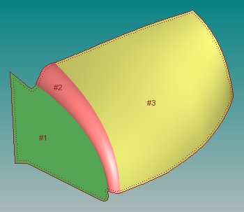
Perimeter scan example

More:

Using the Simulate Pointcloud Function