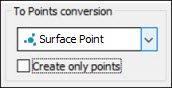
To Points conversion area
The To Points conversion area in the Scan dialog box enables you to create laser Point commands. The commands start from the points that make up the scan.
Hit Type List
The default setting is No Points.
For a Perimeter scan, you can select either Surface Point or Edge Point in the list. For all other types of scans, you can select only Surface Point.
The points are collected in a collapsed GROUP command. The name of the command includes the name of the related scan, the pointcloud associated with it, and the point ID preceded by "Edge" (if you selected Edge Point).
Surface Point Group Command Mode Text
The following is an example of a collapsed GROUP command collecting Surface Points:
COP           = COP/DATA,TOTAL SIZE=468492,REDUCED SIZE=468492,
               FINDNOMS=NO,REF,SCN1,,
SCN1           =  FEAT/SCAN,PERIMETER,NUMBER OF HITS=4,
               SHOW HITS=NO,SHOWALLPARAMS=NO,POINTCLOUDID=COP
               MEAS/SCAN
               BASICSCAN/PERIMETER,NUMBER OF HITS=4,
               SHOW HITS=NO,SHOWALLPARAMS=NO
               ENDSCAN
               ENDMEAS/
SCN1_COP_PNT_GRP1=GROUP/SHOWALLPARAMS=NO
               EXECUTION CONTROL=AS MARKED
               ENDGROUP/ID=SCN1_GRP1
The following is an example of a GROUP command collecting Edge Points:
SCN2       =FEAT/SCAN,PERIMETER,NUMBER OF HITS=3,SHOW HITS=NO,SHOWALLPARAMS=NO,POINTCLOUDID=COP
            MEAS/SCAN
            BASICSCAN/PERIMETER,NUMBER OF HITS=3,SHOW HITS=NO,SHOWALLPARAMS=NO
            ENDSCAN
            ENDMEAS/
SCN2_COP_EDGEPNT_GRP2=GROUP/SHOWALLPARAMS=YES
            EXECUTION CONTROL=AS MARKED
PNT5         =FEAT/LASER/EDGE POINT/DEFAULT,CARTESIAN
            THEO/<133.992,0,0>,<0,-1,0>,<0,0,1>
            ACTL/<133.992,0,0>,<0,-1,0>,<0,0,1>
            TARG/<133.992,0,0>,<0,-1,0>,<0,0,1>
            DEPTH=0
            INDENT=1.5
            SPACER=0.5
            SHOW FEATURE PARAMETERS=NO
            SHOW_LASER_PARAMETERS=YES
              REFERENCE ID=COP
              SOUND=OFF
              HORIZONTAL CLIPPING=3,VERTICAL CLIPPING=3
              REMOVE POINTS WITH NORMALS OUTSIDE=ON,10
PNT6       =FEAT/LASER/EDGE POINT/DEFAULT,CARTESIAN
            THEO/<138.992,0,0>,<0,-1,0>,<0,0,1>
            ACTL/<138.992,0,0>,<0,-1,0>,<0,0,1>
            TARG/<138.992,0,0>,<0,-1,0>,<0,0,1>
            DEPTH=0
            INDENT=1.5
            SPACER=0.5
            SHOW FEATURE PARAMETERS=NO
            SHOW_LASER_PARAMETERS=YES
              REFERENCE ID=COP
              SOUND=OFF
              HORIZONTAL CLIPPING=3,VERTICAL CLIPPING=3
              REMOVE POINTS WITH NORMALS OUTSIDE=ON,10
PNT7       =FEAT/LASER/EDGE POINT/DEFAULT,CARTESIAN
            THEO/<143.992,0,0>,<0,-1,0>,<0,0,1>
            ACTL/<143.992,0,0>,<0,-1,0>,<0,0,1>
            TARG/<143.992,0,0>,<0,-1,0>,<0,0,1>
            DEPTH=0
            INDENT=1.5
            SPACER=0.5
            SHOW FEATURE PARAMETERS=NO
            SHOW_LASER_PARAMETERS=YES
              REFERENCE ID=COP
              SOUND=OFF
              HORIZONTAL CLIPPING=3,VERTICAL CLIPPING=3
              REMOVE POINTS WITH NORMALS OUTSIDE=ON,10
            ENDGROUP/ID=SCN2_COP_EDGEPNT_GRP2
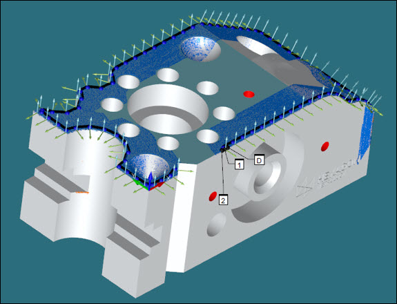
Surface Points and Edge Points are extracted from the COP that you specified in the scan.
Consider the following figures that show Surface Points and Edge Points extracted from a COP using the Scan dialog box for a Perimeter scan:

Create only points
If you select the Create only points check box, PC-DMIS does not create the scan command. In this case, the GROUP command does not contain the name of the scan.
The SCAN command precedes the GROUP command in the Edit window if you create both commands.