The 6 Point Alignment allows you to perform an iterative 3D Best Fit alignment. The following steps outline a typical procedure that would be used to establish a 6 Point Alignment:
Measure three points on the top surface to level to the Z Axis.
Measure two points on the front surface to rotate to the X Axis.
Finally, measure one point to define the origin for the Y axis.
Click Finish. This establishes the correct origin for the alignment.
PC-DMIS inserts the Best Fit 3D Alignment. Following execution, PC-DMIS displays a 3D Alignment Best Fit Graphical Analysis in the Report window.
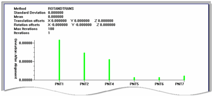
A Sample Best Fit Alignment Graphical Analysis
This graphical analysis of the 3D Best Fit alignment displays this information in the Report window:
Header: This contains various values used in the Best Fit alignment: Method, Standard Deviation, Mean, Translation offsets, Rotation offsets, Max iterations, Iterations.
Vertical Axis: This shows the amount of deviation after the alignment.
Horizontal Axis: This displays the IDs of the points used in the alignment.