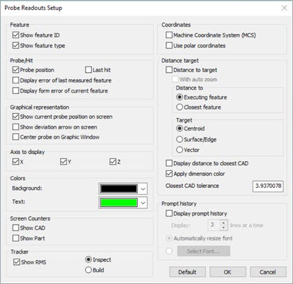
The Probe Readouts Setup dialog box has various options that you can use to work with Leica trackers. This topic discusses a few key options that relate to using the Leica tracker.
To access the Probe Readout Setup dialog box, select the Edit | Preferences | Probe Readout Setup menu item. To access this dialog box directly from the Probe Readouts window, right-click and select Setup.
For more information on the Probe Readout Setup dialog box, see "Setting Up the Probe Readouts Window" in the "Setting Your Preferences" chapter in the PC-DMIS Core documentation.
Probe Readout Setup dialog box
Show Feature ID - Displays the Feature ID for the feature being executed, or the closest feature depending on the Display distance to closest CAD option.
Show Feature Type - Displays the type of feature that corresponds to the feature being executed.
Show current probe position on screen - Displays a 3D representation of the current position in the Graphic Display window.
Show deviation arrow on screen - Displays a 3D arrow in the Graphic Display window that indicates the direction of deviation. The tail of the arrow is always drawn to the probe location in inspect mode and the measured point in build mode.
Center Probe on graphic window - The graphical representation of the current probe always appears in the center of the Graphic Display window.
Distance to Target - This is an execute-only option. In execute mode, it shows the distance from the probe to the feature being executed or the closest feature depending on the Display distance to closest CAD option.
Distance to... Executing Feature or Closest Feature - This option allows you to display the currently executing feature ID or the feature ID for the closest feature to your current probe location. The distance to that feature updates according to the feature selected (executing or closest).
Target - Selecting Centroid calculates the distance to the centroid of the feature. Selecting Surface/Edge point calculates the distance to the point, which is on the feature or CAD element and closest to the centroid.
Display Distance to closest CAD - Shows the distance from the probe to the closest CAD element.
Apply dimension color - This check box changes the colors of the deviation values (Distance to Target values) to match the out-of-tolerance dimension colors.
Show RMS - Displays the RMS value as you take hits.
 Inspect / Build
mode - By default (Inspect mode), PC-DMIS displays
the deviation (T) as Difference = Actual - Nominal.
Inspect / Build
mode - By default (Inspect mode), PC-DMIS displays
the deviation (T) as Difference = Actual - Nominal.
Build Mode - The general purpose is to provide real-time deviations between a real object and its nominal data or CAD model. This allows you to position your part as it relates to the CAD design data.
This option displays the distance and direction that you need to move the measured point to reach the nominal position or Difference = Nominal - Actual.
When you move the part into position, PC-DMIS just displays real-time deviations without storing any data (taking hits). After the part is positioned within a reasonable deviation (such as 0.1mm), you would typically take hits to measure the final position of the feature.
Inspect Mode - In this mode, the position of an object (point, line of surface, etc.) is checked and compared with design data.