The T-Probe represents a free and movable target device to measure with the Laser Tracker and the T-Cam simultaneously. The reflector in the center of the T-Probe is responsible for providing the initial distance measurement of the Absolute Distance Meter (ADM) and the tracking measurement of the Interferometer (IFM). It also receives system command and control signals from the tracker.
See the documentation that came with your T-Probe for detailed information.
Ten (10) IR LEDs with unique IDs are distributed on the T-Probe to provide real-time feedback for measurement procedures. The T-Probe is working in either measurement mode or communication mode.
Measurement mode provides that when the laser beam is locked on the reflector that measurements can be taken.
Communication mode uses strobing sequences from the LEDs to communicate information back to the LT controller.
Before measurement can take place, the T-Probe battery indicator must be solid green (when it is connected to the tracker with a cable) or flashing green (using a battery without a cable). The status indicator must also be green.
PC-DMIS automatically recognizes the T-Probe, unlike reflectors. PC-DMIS marks the currently-active T-Probe in the Probes list of the Settings Toolbar in a bold font face. If you select a different probe from the list that isn't the physically active T-Probe and then take a hit, PC-DMIS displays a warning message. It is recommended to always use the probe settings of the physically active probe; otherwise, your hit data might not be properly corrected for the ball diameter and offset.
To measure points, follow these steps:
Attach the needed stylus to the T-Probe.
Switch on the power to the T-Probe.
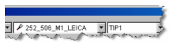
Capture the laser beam in the T-Probe reflector. PC-DMIS automatically detects the Leica T-Probe. The serial number of the T-Probe, the stylus assembly, and the respective mount are visualized on the Settings toolbar and in the Graphic Display window.
Detected T-Probe Serial Number 252, Stylus Assembly 506, Mount 1
Move to the location of the point to measure while you maintain the laser beam visibility.
Record a hit or execute a scan according to the "T-Probe Button Assignments" topic.
If the RMS value for a hit is out-of-tolerance as defined by the RMSToleranceInMM Settings Editor entry, PC-DMIS executes the action specified by the RMSOutTolAction entry. The available actions are: 0 = Accept hit, 1 = Reject hit, 2 = Prompt to accept or reject hit. For details on these Settings Editor entries, see RMSToleranceInMM and RMSOutTolAction topics in the USER_Option section of the PC-DMIS Settings Editor documentation.