To create a nominal point (n-point) Best Fit alignment:
Create or import the nominal point data. For more information, see "Importing Nominal Data".
If you use nominal data for Leica Reflector offsets and supports, ensure that the probe compensation command in the Edit window is set to Off. The probe compensation command needs to be above the points in the measurement routine.
Execute the measurement routine. To execute it, press Ctrl + Q, or select the File | Execute menu item.
The Execution dialog box opens and guides you through the remaining measurements. You can skip points if needed. When PC-DMIS completes all measurements, the dialog box closes. For information on this dialog box, see "Using the Execution Dialog Box" topic in the "Using Advanced File Options" chapter in the PC-DMIS Core documentation.
Insert a Best Fit alignment. To do this, select Alignments | Align Free from the Quick Start interface, or select the Insert | Alignment | New menu item. The Alignment Utilities dialog box opens.
The Alignment Utilities dialog box provides the most flexible way to create alignments, but it requires some experience.
Click Best Fit.
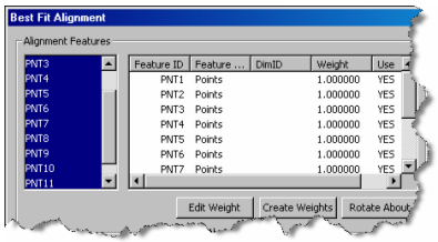
Select all of the features that should be used in the Best Fit alignment.
Best Fit Alignment dialog box - Selecting features
Exclude nominals for axes of selected input features for which theoretical values are not known. To do this, select "NO" under the axis column that should be excluded. This is useful when you only know the theoretical values for one or two of the axes rather than all three.
Ensure that the correct options are set. In this example, PC-DMIS creates a Least Squares 3D alignment. By default, the 3 Dimensional orientation option is selected for trackers.
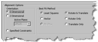
Best Fit Alignment dialog box - alignment options
Click OK to compute the Best Fit alignment and insert the command into the measurement routine. The overall results of the transformation appear in the standard PC-DMIS report. The report uses the Enhanced BFAnalysis ActiveX control plus a new label. This new control adds a grid of the results of each input both before and after the alignment, as well as the axes that were used in the calculations.
Since the alignment command comes after the measured features in the measurement routine, the measured points are still presented in the previous coordinate system. To get the contributing point deviations in the newly-created, active coordinate system, insert Location dimensions into the measurement routine after the alignment command.