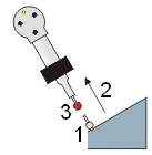
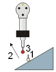
For a portable arm device, follow this procedure to measure a point using a "pulled hit" for probe compensation:
Place the probe on the surface at the point location (1). The probe shaft vector does not matter when you perform a pulled hit.
Either example will work for pulled hits
Press and hold the hit button long enough to get a pulled hit, but not so long that PC-DMIS starts scanning the part. To change the length of time to distinguish between "pulled hit" or "start scanning", you can modify the DelayToStartSendingScanPointsToManualHit entry in PC-DMIS Settings Editor. See "About the Settings Editor - Introduction".
Move the tip in the direction of the vector (2), away from the hit location. You must move it a distance equal to or greater than the defined vector distance (3). To define the minimum distance you must move the probe from the hit to register a pulled hit, modify the VectorToIMM entry in PC-DMIS Settings Editor. See "About the Settings Editor - Intorduction".
Release the hit button, and the computer emits a different lower audible tone. Notice that the software inserts the measured point into the Edit window.
With the point highlighted, press F9 to open the Measured Point dialog box. Verify that the vector follows the PULL direction, not the shaft direction.
For Auto features, the last hit vector determines the compensation direction. For Measured features, the first hit vector determines the compensation direction.
Supported Interfaces
The following interfaces support pulled hits:
SMXLaser (Faro tracker)