Reflector definitions together with the surface offsets are automatically received from the emScon server and are all available from the Settings toolbar. There is no need to define any new probes once the standard reflectors are being used.
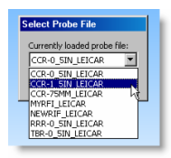
Once the Tracker system detects a reflector, the Select Probe File dialog box appears. This enables you to select the appropriate reflector.
Probe compensation and offset direction
To scan a surface or feature using a reflector, you need to be in scan mode. To do this, select the Operation | Start/Stop Continuous Mode menu item to start continuous mode.
Continuous mode allows you to take incremental points for the reflector location.
To execute scanning, press Ctrl + I when you use a reflector.
To stop continuous scanning, press Ctrl + I again.
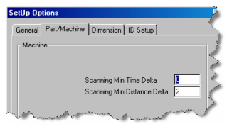
You can set the Scanning Minimum Time Delta and Scanning Minimum Distance Delta from the Part/Machine tab of the Setup Options dialog box (Edit | Preferences | Setup). The default value for point distance separation is 2 mm.
Advanced Scanning
There are many advanced scans possible like sections, multi-sections, etc. Create scans from the Insert | Scan menu. For information, see the "Advanced Scans" subtopic in the "Scanning Your Part: Introduction" topic in the "Scanning Your Part" chapter in the PC-DMIS Core documentation.