Step 2: Calibrate the Laser Probe

The calibration process that this step describes varies based on the type of measure laser probe options and the type of installed interface. For detailed information on calibration options, refer to the "Measure Laser Probe Options" topic in the PC-DMIS Laser documentation.

The following steps outline the procedure to use when you first calibrate your laser probe:

  1. Once the tip is defined in step 1, click Measure from the Probe Utilities dialog box. This opens the Measure Laser Probe Options dialog box.

  2. Click Measure to begin the calibration procedure. If you are NOT using a Perceptron V5 sensor, skip to step 5. If you are using a Perceptron V5 sensor, you are first prompted to scan the entire range of the laser's Z depth on a flat target.

Starting with PC-DMIS 2019 R2, PC-DMIS no longer supports the Perceptron laser sensor. While you may still be able to install PC-DMIS 2019 R2 and later, PC-DMIS displays an error if you attempt to run measurement routines that use the Perceptron scanner. For additional information, please contact Technical Support.

  1. Measure the Z-depth of your V5 sensor (flat target calibration) by doing the following:

  1. Place a white piece of paper on a flat surface where you intend to perform the flat target calibration.

  2. Hold the V5 sensor close to the flat surface so the scan line is beyond the laser's projected grid box.

  3. Press and hold the sensor's trigger while you move the probe away to the full extent of the laser's range so that the laser line crosses the grid box to the other side.

  4. Release the trigger. This completes the flat target calibration.

  1. Follow any on-screen instructions and visual indicators from the Laser tab to complete the sensor calibration on the calibration sphere.

    1. You are prompted to move the probe to 15 different locations on the calibration sphere (5 different positions around the sphere with 3 different fields at each position). The laser probe will continually be probing, but it only accepts a stripe of data when certain criteria are met. The system needs 5 stripes of data at each of the 15 different locations to complete the calibration.

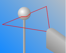
      When you calibrate in the three fields ("far", "left", and "right") for the 5 different positions, be sure to take a hit (laser stripe) at both of the tropics. The tropics are indicated as "Band 1" and "Band 2" in the above image located in the drop-down link). Also, when you probe at 0, 120, and 240 degrees around the equator, favor the lower part of the sphere by taking 2 stripes on the lower location and only 1 on the upper location. This is because additional data will be taken during sets 4 and 5 which occur on the top of the sphere.

    2. For each hit (or laser stripe) of the calibration, use the Laser tab to align the red arc of the laser with the yellow arc (representing the sphere's theoretical arc) so the form and size match as close as possible.

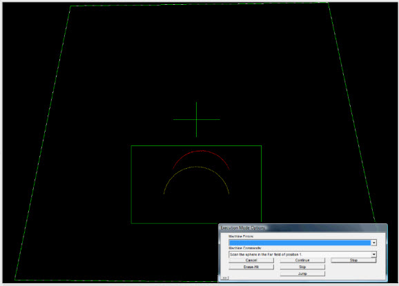
    3. Move the laser's red arc so that it remains within the green rectangular box surrounding the yellow arc. As you position the laser's arc on top of the yellow arc, an audible beeping sound increases in frequency and pitch. This helps you know when you are approaching the desired location.

  1. Hold the laser probe motionless at the appropriate location until the various criteria are met. PC-DMIS automatically accepts the stripe and prompts you to probe at a new location.

Next Step ...