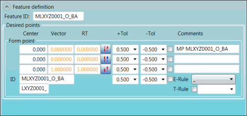
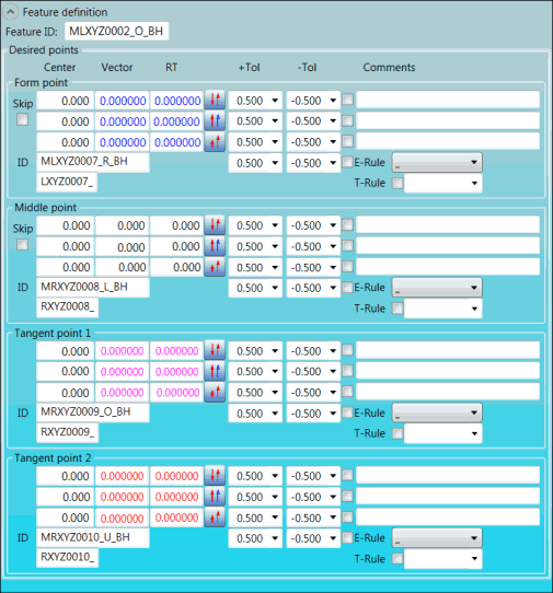
Desired
points |
When you hover your pointer over
an option in this area, a screen tip about the option appears.
These areas all share the items described
below:
Form
point area
Middle point area
Tangent point 1 area
Tangent point 2 area
Center boxes:
These boxes display the X, Y, and Z coordinates of the feature. Vector boxes:
These boxes display the I, J, and K values of the feature's
vector for the measurement. RT boxes:
Type the I, J, and K values of the feature's RT (report vector)
for the evaluation of the point. +Tol lists:
Select the upper tolerances for the X, Y, Z, and RT dimension
axes. -Tol lists:
Select the lower tolerances for the X, Y, Z, and RT dimension
axes. Output X-axis,
Output Y-axis, Output
Z-axis, and Output RT-axis
check boxes: To print tolerances to the Edit window and to
reports (when PC-DMIS is set up to store information in a
format to be viewed textually), select the check box for each
tolerance that you want to print. The check box for each axis
that needs to be evaluated, according to the option you select
in the E-Rule list, is automatically
selected (and greyed out). You can change these check boxes
only by selecting a different option in the E-Rule
list. Comments
boxes: Type comments in these boxes. The comments appear in
front of the dimensions in reports when PC-DMIS is set up
to store information in a format to be viewed textually. E-Rule list:
Select the E-Rule (evaluation rule), which defines the axis
that is tolerated. To view the description of an option, hover
your pointer over the option. The option that you select becomes
part of the ID in the ID box. T-Rule box:
Use this box to save the current tolerances in a T-Rule (tolerance
rule). This is useful for tolerances that are used often,
such as -0.3 and 0.3. You can also recall the tolerances for
an existing T-Rule and delete a T-Rule.
To save
the current tolerances in the +Tol
and -Tol lists, type a name for
the T-Rule in the T-Rule box, right-click
in the box, and select Save.

Save and Delete options
The T-Rule appears
in the list.
To recall
the tolerances for an existing T-Rule, select the rule in
the list. To delete
a T-Rule, select the rule that you want to delete, right-click,
and select Delete.
|


