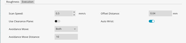
To set the execution parameters for the Roughness scan command (RGHSCN), select the Execution tab in the Roughness Scan dialog box (Insert | Scan | Roughness):
Execution tab
Scan Speed list - Select the speed at which the PROFILER R sensor can scan the part. For more information about this sensor, see "PROFILER R Roughness Sensor".
Offset Distance box - The offset distance determines the force with which the probe is held on to the part during the scan. Usually, this distance is set equal to the recommended value for the type of probe head on your machine. You should not change the offset distance unless you are very experienced with the machine and its parameters.
Use Clearance Plane switch - This switch is available if a clearance plane is active in your measurement routine. If you turn this switch to On, the Roughness scan command adds a Move Clear Plane command (MOVE/CLEARPLANE) directly before the Roughness scan command in the Edit window. For more information about this command, refer to the "Inserting a Move Clear Plane Command" topic in the "Inserting Move Commands" chapter in the PC-DMIS Core documentation.
Avoidance Move list - Select the avoidance move:
None - No avoidance moves will be used for the current feature.
Both - Before PC-DMIS measures the support point, it will first move to the specified distance above the support point, and it will move to the specified distance above the support point after the roughness scan.
Before - Before PC-DMIS measures the support point, it will first move to the specified distance above the support point.
After - After PC-DMIS completes the roughness scan, it will move to the specified distance above the support point.
Avoidance Move Distance box - The value you enter in this box defines the distance above the support point that the probe moves to during execution.
Auto Wrist switch - If you turn this switch to On, PC-DMIS calculates the best A and B angle of the wrist to measure the roughness. With this switch set to On, and if you have a rotary table that uses a horizontal sensor, the auto wrist calculates the combination of the A, B, and RT angle W. PC-DMIS then inserts the required tip and Move/Rotab commands above the Roughness scan command. If you turn this switch to Off, PC-DMIS does not calculate the best angles required.
This option is only for Plane surface type. You cannot use this option to measure roughness inside a small hole.
Rotary Table
The roughness scan command supports the use of rotary table with 90TR (Horizontal) type of sensors. The roughness scan command determines the best combination of rotary table in combination with A and B angles for the desired roughness scan. The use of a rotary table helps to measure the roughness on most surfaces of the part.
In order to use a rotary table, you need to set the following items:
You must define the rotary table in PC-DMIS (for more details, see Edit | Preferences | Setup)
The IGNOREROTAB command must be set to OFF.
IGNOREROTAB/OFF
You must set the Auto wrist switch on the Execution tab of the Roughness scan dialog box to On.
If you create the Roughness scan as described above, PC-DMIS inserts the MOVEROTAB command if needed.
PC-DMIS tries to first find the angle at the current position of the rotary table. If there is no physical A and B angle positions of the sensor available to measure the desired roughness scan, PC-DMIS then tries to find the position of the rotary table in combination with the A and B angle positions to measure the roughness.
If the Use Clearance Plane switch is set to ON, the software inserts the Move/Clearplane command before the Move/Rotab command.
More: