Step 1: Manually Measure an Edge Point
The manual alignment in this example consists of a
single to approximately
locate the part. In later steps, PC-DMIS measures additional datums (under
DCC if applicable) to create a final alignment. Before you begin, mount
the part so it is reasonably square to the axes of the measuring machine.
To measure the datum feature, do the following:
Select the Magnification
tab  and adjust
the magnification until you decrease it to the minimum setting (zoomed
out).
and adjust
the magnification until you decrease it to the minimum setting (zoomed
out).
Select the Illumination
tab  and set
the Top Light to 0% (Off) and the Bottom Light to 35%.
and set
the Top Light to 0% (Off) and the Bottom Light to 35%.
Select the CAD tab.
From the Graphic Modes
toolbar (View | Toolbars | Graphic Modes),
select the Curve Mode button  .
.
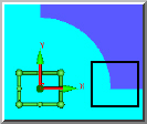
Move the machine so the front-left corner is within the FOV as shown below:
From the Auto Feature
toolbar, click Edge Point to open the Auto Feature (edge point) dialog box.
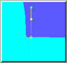
Click a point on the front edge, VERY
CLOSE to the left corner.
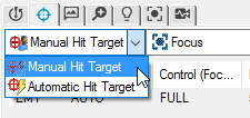
Select the Hit Targets
tab  .
.
Change Automatic Target
to Manual Hit Target.
Since this is actually a "Manual
Target" edge point, the actual point used is where you have physically
placed the crosshair.
Click Create to add
this edge point to the measurement routine.
Click Close to exit
the Auto Feature dialog box.
Next Step ...