Since the features that will comprise the DCC alignments were measured under computer control and the exact corner will be used, this alignment will inherently be more accurate.
To create a DCC alignment:
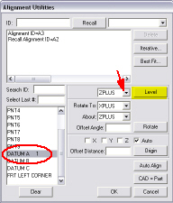
Select the Insert | Alignment | New menu option. The Alignment Utilities dialog box appears.
From the feature list, select DATUM A.
To level the plane to the ZPLUS plane, from the Level drop-down box, select ZPLUS.
Click the Level button. This levels the plane to the ZPLUS axis.
Select DATUM B from the feature list to rotate to the XPLUS axis about the ZPLUS axis.
From the Rotate To drop-down box, select XPLUS.
From the About drop-down box, select ZPLUS.
Click the Rotate button.
Select FRNT LEFT CORNER from the feature list to establish the XYZ origin.
Select the check boxes next
to  X and Y.
Click the Origin button.
Select DATUM A.
Select the check box next to
Z.
Click the Origin button again.
Type ABC in the ID box for the alignment name.
Click OK to exit.