In PC-DMIS Vision, you position targets on a feature to acquire measured points. The type of target used is automatically chosen based on the feature being measured.
In the example below:
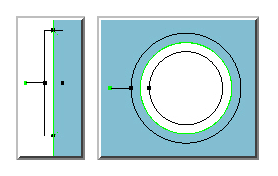
Measuring a line feature uses a rectangular shaped target.
Measuring a circle feature uses a doughnut shaped target.
Line and circle target examples
Features can be measured by one or more targets. In the example below, the line is measured with 3 targets where the middle target is not being used to collect data.
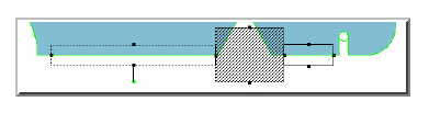
Example of line being measured using three targets
The size of the feature to measure determines the span of the target. For example, a small circle that fits inside of the FOV can be measured with a single target, where a larger circle that exceeds the FOV would require multiple targets to span its circumference. After selecting the Auto feature to be measured, the targets are created by:
Selecting a feature from the CAD model.
Manually entering the nominal values.
Creating Target anchor points.
More information is available in the "Measuring Auto Features with a Vision Probe" topic.