Click Insert | Feature | Auto | Blob from the main menu.
Click the Blob button
 on
the Auto Features toolbar.
on
the Auto Features toolbar.
Overview
To access the Blob Auto Feature dialog box, do one of the following:
Click Insert | Feature | Auto | Blob from the main menu.
Click the Blob button
on
the Auto Features toolbar.
To use the Blob Auto feature, the required feature must fit within the Field of View. The Blob feature is designed to work well on parts that lead to an image with high contrast edges, even illumination, and no significant high-frequency spectral components. For example, it works well on thin, back-lit parts, or on surface-illuminated parts with no significant surface texture.
When you open the Blob dialog box, click the Vision tab to create the target.
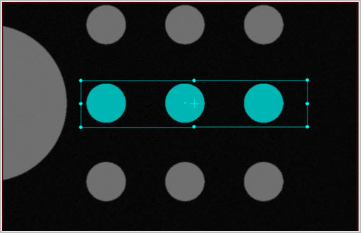
Example of creating the Blob | Auto Feature target in the Live View
Once you create the target, you can re-size it in the same way as other Auto features. PC-DMIS highlights the pixels included in the blob calculation in the Live View.
Creating a Vision Blob feature
For machines that support DCC motion, select
DCC Mode  if you want
to create and measure the Blob | Auto Feature
in DCC mode.
if you want
to create and measure the Blob | Auto Feature
in DCC mode.
Select Auto Blob from the Auto Feature toolbar. You can also select the Insert | Feature | Auto | Blob menu option. This opens the Auto Feature (Blob) dialog box.
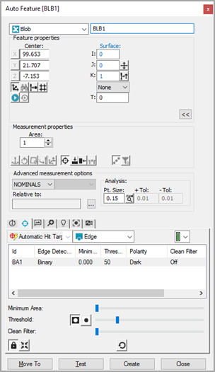
Vision Blob Auto Feature dialog box
With the Auto Feature dialog box open, use the Target Selection method. To do this, from the Vision tab, click once on the surface to establish the point's location. Adjust the lighting and magnification from the Probe Toolbox as needed.
Click as close as possible to the CAD element to ensure PC-DMIS does not choose an incorrect element.
PC-DMIS Vision automatically places the nominal data for the Blob into the Auto Feature dialog box. The software automatically displays the hit targets for the Blob.
Adjust the nominal information in the Auto Feature dialog box to match the theoretical values of the Blob. Also, adjust the values in the Probe Toolbox as needed.
This image and the description below it highlight the important elements when you define the Blob | Auto Feature:
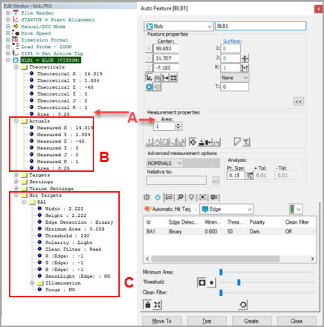
The Theoreticals area allows you to manually enter the nominal Area value in the current measurement routine units.
The Actuals area updates automatically when you execute the measurement routine.
You can set the Blob Auto feature parameters such as Minimum Area, Threshold, Polarity, and Clean Filter in the Hit Targets section of the measurement routine as well as with the respective sliders in the Hit Targets tab of the Blob | Auto Features dialog box (shown below).
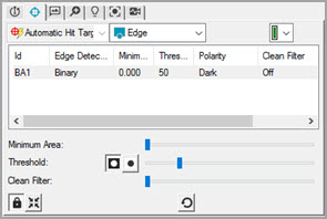
Hits Target tab of the Blob | Auto Feature dialog box
Minimum Area slider - Use the Minimum Area slider to adjust the filter value. The target size determines the scale of the slider as the maximum is set as half the calculated area within the target.
Threshold slider and Polarity buttons - Use these options to determine which pixels the software includes in the feature calculation. If you select the Dark polarity button, the software uses any pixels within the target area below the threshold. If you select the Light polarity button, the software uses any pixels within the target area above the threshold. Use the Threshold slider to set the target area pixel range for the selected polarity button.
Clean Filter slider - Use this option to apply filtering as needed to remove noise such as dust or small dirt. The strength determines the size of the noise to remove. The options are Off, Weak, Medium, and Strong.
When the Hit Targets tab is active in the Probe Toolbox, the software highlights the pixels that form the blob within the live image view. The highlighted pixels automatically update when you change any relevant parameters.
Click Create on the Auto Feature dialog box to add the blob to the measurement routine.
PC-DMIS currently does not support the Blob Auto feature functionality with MultiCapture (for details, see the MultiCapture section in the "Setting up the Live View" vision help topic).
Save the measurement routine for future execution. See "A Note on Executing a Vision Measurement Routine".
Returning the Blob's Area with Expressions
If you need to return the theoretical or measured value for a Blob feature, you can use the .AREA or .TAREA extensions with the Blob's ID. These return the measured area and theoretical area values of the Blob feature respectively. For more information, see the "References of Type Double" topic in the "Using Expressions" chapter in the PC-DMIS Core documentation.
Access to the individual blobs found within the Blob Auto feature is illustrated in the following command examples:
Assign / V1 = blb1.Numhits
Assign / V2 = blb1.hit[C].XYZ
Assign / V3 = blb1.hit[C].AREA
Returning the Blob's Area with the Location Dimension
From the Feature Location dialog box (Insert | Dimension | Location), in the Axes area, you can mark the Area check box to have your report calculate and display a Blob feature's area. It appears as AR in the report and in the Edit window's Command mode. For more information, see the "Dimensioning Location" topic in the "Using Legacy Dimensions" chapter in the PC-DMIS Core documentation.