Vision Line

To create a vision Line, follow these steps:

  1. For machines supporting DCC motion, select DCC Mode if you want to create and measure lines in DCC mode.
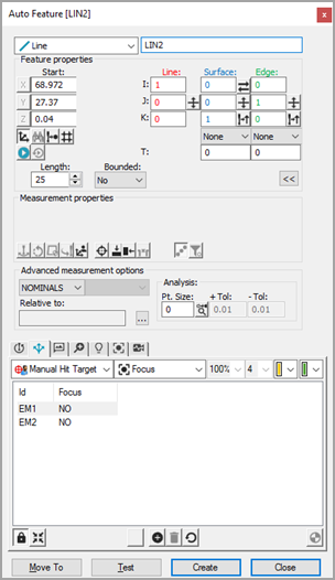
  2. Select Auto Line from the Auto Feature toolbar. You can also select the Insert | Feature | Auto | Line menu option. This opens the Auto Feature (line) dialog box.

Vision Line Auto Feature dialog box

  1. With the Auto Feature dialog box open, select a line in one of two ways:

Click as close as possible to the CAD element to ensure PC-DMIS does not choose an incorrect element.

  1. PC-DMIS Vision automatically places the nominal data for the line into the Auto Feature dialog box. The hit targets are automatically displayed for the line.

  1. Adjust the nominal information in the Auto Feature dialog box to match the theoretical values of the line. Also, adjust the values of the Probe Toolbox as needed.

  2. Click Test to test line measurement.

  3. Click Create on the Auto Feature dialog box to add the line to the measurement routine.

  4. Save the measurement routine for future execution. See "A Note on Executing a Vision Measurement Routine".