Vision Profile 2D
PC-DMIS has an option to switch between the Legacy Profile
2D and the latest version of Profile 2D. For details, see the "Use Legacy
Profile 2D" topic in the "Dimensioning
Features" chapter in the PC-DMIS Core documentation.
Legacy Profile 2D
To create a Legacy Profile 2D, follow these steps:
For machines that support DCC motion, select
the DCC Mode  icon
if you want to create and measure Profile 2D features in DCC mode.
icon
if you want to create and measure Profile 2D features in DCC mode.
To open the Auto Feature
(Profile 2D) dialog box, select the Auto Profile
2D  icon from the Auto Feature toolbar. You
can also select the Insert | Feature | Auto | Profile
2D menu option.
icon from the Auto Feature toolbar. You
can also select the Insert | Feature | Auto | Profile
2D menu option.
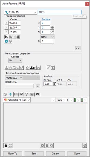
Vision Profile 2D Auto Feature
dialog box
From the Auto Feature
dialog box, select a profile 2D in one of two ways:
CAD
Selection method - From the CAD tab,
click once (in Surface mode) near the edge of the Profile 2D on the
CAD surface to establish the Profile 2D's location. In Curve mode,
you must select each CAD entity that makes up the feature's form.
Target
Selection method - From the Vision tab,
click a sufficient number of points to define the shape of the profile,
with each pair of points being joined by an arc or a line. You can
insert more points later by right-clicking on the target and selecting
Insert Nominal Segment. Or, you may also
double-click in the Vision tab to edge trace.
See the "Using 2D
Profile Edge Tracer" topic. This establishes the Profile
2D's location. Adjust the lighting and magnification as needed.
Click as close as possible to the CAD element to ensure
PC-DMIS does not choose an incorrect element.
PC-DMIS Vision automatically places the nominal
data for the Profile 2D into the Auto Feature
dialog box. The hit targets are automatically displayed for the Profile
2D.
For all features (except for
Profile 2D), the hit targets are automatically displayed for the feature.
For a Profile 2D feature, you need to click on the Show
Hit Targets button on the Auto Feature
dialog box when you’ve defined the profile’s nominal position. See "Required Clicks
for Supported Features".
Adjust the nominal information in the Auto Feature dialog box to match the theoretical
values of the Profile 2D. Also, adjust the values of the Probe
Toolbox as needed.
Click Test to test
the Profile 2D measurement.
Click Create on the
Auto Feature dialog box to add the Profile
2D to the measurement routine.
Save the measurement routine for future execution.
See "A
Note on Executing a Vision Measurement Routine".
More:
Using
Profile 2D Edge Tracer
Non-Legacy (Latest) Profile 2D
The latest version of the Profile 2D has the following
capabilities:
Live View Selection
You can program a Profile 2D feature by double-clicking
near the edge of the feature in the Live View. PC-DMIS Vision automatically
traces around the edge of the feature and moves the machine stage on a
DCC machine if necessary.
Rules for Clicks to Start Edge Tracer
When you double-click an edge, PC-DMIS Vision
traces around the selected edge and attempts to return to the start
position.
If you first single-click a point before double-clicking,
the first clicked point is your start point, and the double-clicked
point is your targeted end point.
If you click two points before double-clicking,
the first click is the start point, and the second click dictates
the direction in which the trace will proceed. The double-click position
will be the end point.
At first-time execution, as there is no Nominal
data and if Master mode is not selected, a dialog box is displayed
stating that Master mode execution is required. You are then prompted
to switch to Master mode. All subsequent executions will be compared
against this data.
If you wish to re-define the Master data, you can switch
Measure Mode to MASTER in the Edit window (or press F9 on the feature)
and select MASTER from the dialog box to display a dialog box that asks
if you want to replace the existing nominal data.
CAD View Selection
Set the Closed option in
the Measurement properties section of the feature
dialog box to Yes to program a Profile 2D feature.
Closed - Setting
this Measurement properties option to Yes
allows a single click on the CAD. Multiple clicks are no longer required.
Open - Setting the
Measurement properties to No allows you
to click the first point. The second point defines the direction,
and the third point defines the end point.
If a Profile 2D feature is created from CAD, it will
always use CAD as nominal.
PC-DMIS will use the CAD objects as the nominal regardless
of the Nominal, Master, or Find Noms Mode choice in the Advanced
Measurement options section of the Auto Feature
dialog box. Even if the mode choice is changed, the feature still uses
the CAD object as nominal.
Targets can be edited after creating the new 2D profile
in the CAD View or Live View by right-clicking within the target to display
a menu. Select or de-select the Edit Nominal Segments
option to turn on or off nominal segment editing. This feature allows
you to adjust or delete existing targets or insert additional targets.
Reporting Material Condition properly when creating
a vision Profile 2D on a CAD wireframe model
To ensure the correct material condition is represented
when creating a vision Profile 2D on a wireframe CAD model:
Outer Profile - The
First, Direction
and End Points should be taken in a clockwise
direction
Inner Profile - The
First, Direction
and End Points should be taken in a counterclockwise
direction
A Closed Contour on a wireframe CAD model should be considered
an Open Contour adhering to the clockwise or counterclockwise convention.
Once programmed with the correct direction, select the Contour
option in the dialog box to close it.
To create a vision Profile 2D on a surface CAD model,
create the Outer or Inner Profile in a clockwise or counterclockwise direction;
the material condition is guaranteed to be correct.