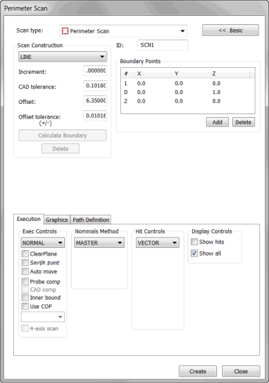

Perimeter Scan dialog box
The Insert | Scan | Perimeter scan differs from other linear scans in that they are created entirely from CAD data before execution. This type of scan is available only when CAD surface data is available. It allows PC-DMIS to know exactly where it is going before it begins (with a small amount of error).

A sample exterior Perimeter Scan
Two Types of Perimeter Scans
Two types of perimeter scans are available:
An exterior scan follows the outside of the selected surface boundary or boundaries. An exterior scan can traverse across multiple surface boundaries to create a single scan.
An interior scan follows a boundary curve inside a given surface. These types of curves usually define features such as holes, slots, or studs. Unlike the exterior scan, an interior scan is limited to the interior of a single surface.
The figures below (Scan 1 and Scan 2) illustrate both types of perimeter scans.
In Scan 1, four surfaces have been selected. Each surface borders another, but the outside of each surface makes up the composite boundary (indicated by the solid red outer line). The offset distance is the amount that the scan will be offset from the composite boundary (indicated by the broken red line).

Scan 1
A - Surface 1
B - Surface 2
C - Surface 3
D - Surface 4
In Scan 2, the boundary of a hole creates the path for an interior perimeter scan.

Scan 2
The procedure for creating an exterior or interior scan is the same and is outlined below.
To create a perimeter scan, follow these steps:
Access the Perimeter Scan dialog box (Insert | Scan | Perimeter).
If you want to use a custom name, type the name of the scan in the ID box.
For interior perimeter scans, select the Inner Bound check box on the Execution tab.
Select the surface(s) to use to create the boundary. If you select multiple surfaces, you should select the surfaces in the same order that they are to be traversed by the scan. To select the necessary surface(s):
Verify that the Select check box is selected on the Graphics tab.
Click, in turn, the surfaces that you want to use in the scan. Each surface highlights as you select it.
After you select the desired surfaces, clear the Select check box.
Click on the surface near the boundary where the scan is to begin. This is the start point.
Click on the same surface a second time in the direction that the scan will execute. This is the direction point.
If desired, click on the point where the scan is to end. This point is optional. If you do not provide an End Point, the scan will end at its start point.
PC-DMIS automatically provides an end point. If this end point won't be used, delete it. To delete it, highlight the number (the default is 2) in the Boundary Points list and click the Delete button.
Type the appropriate values into the Scan Construction area. These include the following:
Increment box
CAD Tol box
Offset box
Offset Tol (+/-) box
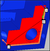
Select the Calculate Boundary button. This button calculates the boundary from which PC-DMIS will create the scan. The orange dots on the boundary indicate where the hits are taken on the perimeter scan.
The boundary calculation should be a relatively quick process.
If the boundary does not look correct:
Click the Delete button. This deletes the boundary and allows another to be created. (If the boundary appears incorrect, it usually means that the CAD tolerance needs to be increased.)
After you increase the CAD tolerance, click the Calculate Boundary button to recalculate the boundary.
Verify that the boundary is correct before you calculate a perimeter scan because it takes much longer to calculate the scan path than it does to recalculate the boundary.
Verify that the Offset value is correct.
Click the Generate button in the Theoretical Path area on the Path Definition tab. PC-DMIS will then calculate the theoretical values that will be used to execute the scan. This process involves a very time intensive algorithm. Depending on the complexity of the selected surfaces and the amount of points that are being calculated, it may take a while to compute the scan path. (A five minute wait is not uncommon.) If the scan does not appear correct, click the Undo button to delete the proposed scan path. As needed, alter the Offset Tolerance value and recalculate the scan.
If needed, you can delete individual points. To do this, select them one at a time from the Theoretical Path area and press the Delete key.
Click the Create button to create the perimeter scans and store it in the Edit window. It will be executed like any other scan. If you have the PC-DMIS AutoWrist method enabled but don't have any calibrated tips, PC-DMIS will display a message informing you when it adds new probe tips that need calibration. In all other cases PC-DMIS will ask you whether it should use the closest calibrated tip to the needed tip angle or add in a new non-calibrated tip at the needed angle.
Note on Hole Avoidance
Be aware that Defined mode in the Exec Controls area on the Execution tab does not support hole avoidance with Perimeter scans. Ensure that there aren't any holes in your scan's pathway with this execution mode. If there are, either adjust your path or switch to the Normal execution mode.