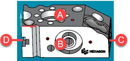
This tutorial uses this Hexagon test block and CAD model.

This documentation refers to the above labeled faces as:
A - The top face
B - The front face
C - The right face
D - The left face
Connect this part to your CMM. You need to elevate it above the table so that the probe body can measure features on the side faces without hitting the CMM table. Also, be sure to connect a probe with a wrist to your CMM.
 More Info
Go to the next step: "Start Up and Home the CMM"