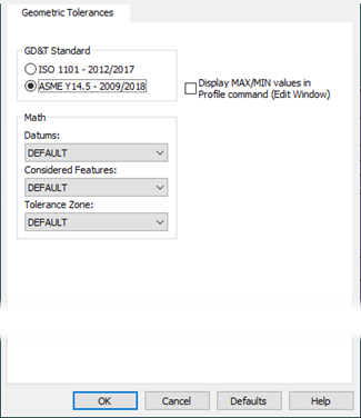
Setup Options dialog box-Geometric Tolerances tab
The Geometric Tolerances tab controls several defaults for the creation of new geometric tolerance commands. For more information on geometric tolerance commands, see the "Using Geometric Tolerances" chapter.
GD&T Standard - This area shows the available standards that you can set as the default standard that you want new geometric tolerance commands to use. When you create a new geometric tolerance command, or access the Geometric Tolerance dialog box, PC-DMIS automatically selects the standard that you set here (ASME Y14.5 or ISO 1101).
Starting with PC-DMIS 2023.2, you are no longer able to toggle the selected GD&T standard from within Geometric Tolerance commands. For details, see "Comparison to Past Practices - Referencing the GD&T Standard" section of the "Structuring your Measurement Routine for Geometric Tolerances" topic.
This tab is the only place where you can change the GD&T standard. Starting with 2023.2, PC-DMIS no longer attempts to convert between ASME and ISO standards. In the past, this was somewhat possible due to the limited level of support of ISO functionality in PC-DMIS. With the expanded development of ISO capabilities in PC-DMIS, divergence from the ASME standard has become increasingly significant. In many cases to the point where no equivalency exists between the standards, causing conversion to be impossible.
You can change the selected GD&T standard at any time while programming but, since the setting applies to the entire routine, you will encounter different behavior depending on the routine's content at the time of the change.
If there are no Geometric Tolerance or Size commands in the measurement routine, you can change the GD&T standard from the Geometric Tolerances tab of the Setup Options dialog box (Edit | Preferences | Setup), and it becomes the default standard going forward. PC-DMIS updates the program header to reflect the GD&T standard that is now referenced and uses the standard for all new Geometric Tolerance and Size commands you create.
If the measurement routine contains existing Geometric Tolerance or Size commands and you attempt to change the GD&T standard from the Geometric Tolerances tab of the Setup Options dialog, PC-DMIS shows this warning:
PC-DMIS
All Geometric Tolerances and Size commands within a measurement routine must reference the same GD&T standard. Once you click OK, PC-DMIS disables any pre-existing Geometric Tolerance and Size commands in the measurement routine. After the conversion finishes, you must then recreate these commands. Click OK to continue or click Cancel to abort this operation.
If you click Cancel, the GD&T standard does not change and your measurement routine remains in its current state.
If you click OK to continue, the GD&T standard for the routine changes to the one you selected. It becomes the default standard for all new Geometric Tolerance and Size commands and the program header updates in the Edit window to reflect this change. PC-DMIS renders all existing Geometric Tolerance and Size commands as invalid and displays them in red in the Edit window. You cannot edit or execute these commands. Any dependent commands will no longer function.
The main purpose in preserving these commands is to allow you to re-create them and reference them using the newly selected GD&T standard. Once completed, you can then delete the invalid commands and update the dependent commands to reference the new commands.
Math - As discussed in the "Using Geometric Tolerances" chapter, geometric tolerance commands have three kinds of math options:
Datum math options
Considered feature math options
Tolerance zone math options
This Math area lets you define what math options you want PC-DMIS to use for new geometric tolerance commands. You can change the math options in individual geometric tolerance commands, and it does not affect future geometric tolerances that you create, nor does it affect what you set here.
For information on how to choose the math options for your application, see the "Using Geometric Tolerances" chapter.
Profiles display MAX/MIN values in Profile command (Edit Window) - This check box defines whether PC-DMIS displays the minimum and maximum deviation values in profile tolerance commands inside the Edit window.
If you clear this check box, geometric tolerance commands that represent profile tolerances display a single measured value. This value is based on the single actual value defined by the GD&T standard you selected.
If you select this check box, profile tolerances show the minimum and maximum deviation values instead of the single measured value.
This setting does not affect the report. Geometric Tolerance report labels for Profile of a Surface and Profile of a Line always report the single measured value, regardless of the Profiles display MAX/MIN values in Profile command setting.