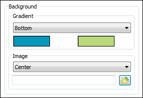

This area applies to the Colors tab of the CAD and Graphic Setup dialog box (Edit | Graphic Display Window | Screen Color).
The Background area allows you to change the background screen color or set an image as the background. PC-DMIS also uses the color or image as the background for any Geometric Tolerances displayed in the Graphic Display window. Follow the directions discussed in "To Change a Color" to set the background color.
Setting the Gradient Background Color
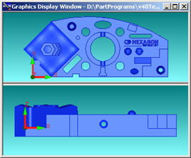
The Gradient area lets you define a secondary background gradient color. When you set the gradient to something other than None in the list, a rectangular color box appears. You can click that box to define a secondary gradient color. Then, when setting the screen's background, PC-DMIS starts from the setting location (for example, the Bottom) and displays the secondary gradient color, and then gradually changes from that color to the primary gradient color as it draws the colors near the other end of the screen.
For example, a Bottom gradient setting might look like this:

Gradient Colors Example
The available items in the Gradient list are:
None - No secondary gradient. The screen's background will be the solid primary color.
Bottom - The secondary gradient color starts at the bottom of the screen and gradually changes to the primary color as it nears the top.
Right - The secondary gradient color starts at the right side of the screen and gradually changes to the primary color as it nears the left side.
Top left - The secondary gradient color starts at the top-left side of the screen and gradually changes to the primary color as it nears the bottom right side.
Top right - The secondary gradient color starts at the top right side of the screen and gradually changes to the primary color as it nears the bottom-left side.
Bottom Left - The secondary gradient color starts at the bottom-left side of the screen and gradually changes to the primary color as it nears the top-right side.
Bottom Right - The secondary gradient color starts at the bottom-right side of the screen and gradually changes to the primary color as it nears the top-left side.
Setting an Image as the Background
The Image settings area sets
an image as the background. To do this, from the Image
Mode drop-down list, set the image to something other than None. This enables the File
Navigation text box and the Open File
button  . Then, do one of the following:
Manually enter the path to the image file in the File Navigation text box then click OK on the CAD and Graphic Setup dialog box.
or:
Click Open File to display the Open dialog box, navigate to the image file and then select it. Click Open from the Open dialog box, and then click OK on the CAD and Graphic Setup dialog box.
The background image is drawn based on the image mode selected:
None - No background image is displayed.
Center - The image is centered in the Graphic Display window and is not scaled.
Top left - The image is positioned at the top-left of the Graphic Display window and is not scaled.
Top right - The image is positioned at the top-right of the Graphic Display window and is not scaled.
Bottom left - The image is positioned at the bottom-left of the Graphic Display window and is not scaled.
Bottom right - The image is positioned at the bottom-right of the Graphic Display window and is not scaled.
Fit - The image is scaled to fit just inside the Graphic Display window, preserving the image's aspect ratio.
Stretch - The image is scaled to fill the entire Graphic Display window, not preserving the image's aspect ratio.
Fill - The image is scaled to fill the entire Graphic Display window, preserving the image's aspect ratio.
Tile - The image is drawn repeatedly over the entire Graphic Display window and is not scaled.
Tile mirrored - The image is drawn repeatedly over the entire Graphic Display window with every other image being mirrored. The images are not scaled.