Step 4 - Define the Ports
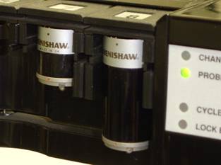
The example described below has a probe extension in port 7 and port 8. When you use a probe extension such as these, you must identify and define it prior to calibration.
To define the ports of your ACR1 Probe Changer, do the following:
Select the Ports tab in the Probe Changer dialog box (Edit | Preferences | Probe Changer). When you first identify the probe changer, the list shows all of the ports as UNDEFINED:
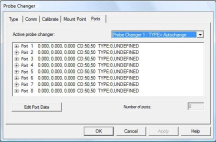
Probe Changer dialog box - Ports tab with undefined ports
You must define all of the ports in the probe changer before you start.
In the Active probe changer list, select TYPE= Autochange.
Select a port in the list, and click Edit Port Data. The Probe Changer Port Data dialog box appears:
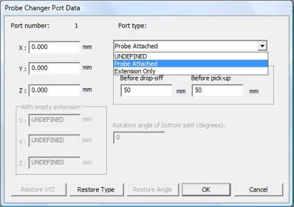
Probe Changer Port Data dialog box with Port type selection options
For each port, you need to classify its contents as either "Probe Attached" or "Extension Only". In the Port type list, select the appropriate option:
Probe Attached - Only probe bodies are in the ports, or the port is empty.
Extension Only - The port contains a probe extension (Renishaw PEM Autojoint to Autojoint Extension Bar, commonly called PEM). The PEM is available in various lengths, but the length is not significant at this point.
You can specify the XYZ values for the center position of the port, or leave those values empty. In any case, PC-DMIS automatically populates these values upon successful calibration. See "Step 10 - Review the Calibration Results".
To save your changes to the port data and close the Probe Changer Port Data dialog box, click OK. Repeat steps 4 and 5 for all ports in your probe changer.
In the example below, ports 1 through 6 have been defined as containing only a probe body. Ports 7 and 8 are identified as each holding a PEM probe extension. It is not necessary that they be in adjacent ports; this is for illustration purposes only.
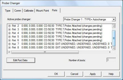
Probe Changer dialog box - Ports tab with the ports defined
To save your changes, click Apply.
You are now ready to begin calibration. The next step starts the calibration process.