
(This item pertains to the Custom Probe Builder Utility, accessible through Edit | Preferences | Custom Probe Builder Utility.)
You can use the Assemble tab to assemble a custom probe component.
Custom Probe Builder Utility - Assemble tab
To create an assembly from various components:
From the Probe File section, select a file.
From the Connection Type list, select the appropriate type of connection.
From the Component Selection list, select a component. The software updates the list based on the Probe File selection. The software uses the list to create an assembled component from the files, and then it sorts all the items in the list by their connection types. For example, if Connection #1 is defined as an M8 connection, only items that can connect to an M8 connection are available in the list.

Custom Probe Builder Utility - Assemble tab showing the start of an assembly build
For example, in the Assemble tab shown above:
The "probe.dat" file is selected in the Probe File area.
The "ADAPTER28MM_Ren" component (found in the "probe.dat" file) is selected from the Component Selection list.
The component is drawn in the graphic area. The red dot identifies the first available (empty) connection. You can zoom and rotate the image. For example, if you press Ctrl + Z on your keyboard, the software zooms the image to fit entirely within the graphic area.
The Assembled Components area displays a tree view of the selected component and highlights the first empty connection. Each time you fill an empty connection, the software automatically selects the next available empty connection port. To remove a connection, you can left-click the item, and then click Delete.
Once you add a component to the Assembled Components tree, the software enables the Delete, Clear, and Save IGES buttons.
From the Probe File area, select another file or use the currently selected file to continue to build the assembly.
At any point, you can change the Probe File option and select items you created in the Component Builder tab.
Custom Probe Builder Utility - Assemble tab showing the continuation of an assembly build
From the Connection Type list, select a new connection type. If an assembly already exists, a prompt asks if you want to clear the current build. Click Yes to clear the build and start over, or click No to return to the current build.
From the Component Selection list, select new components to add to the connections. Some components may have more connections that you can add onto, while others may end with terminating elements (Spheres, Disks and Shanks) as shown below:
Custom Probe Builder Utility - Assemble tab showing the completion of an assembly build
Update the assembly with any of these options:
The Delete button works similar to the Delete button on the Probe Utilities dialog box. If you build a branch on the tree that contains multiple items, you can delete the entire branch or just portions of it. The Delete button only removes the selected item in the tree along with any attached components.
The Clear button clears the entire tree and the graphic area.
The Save IGES button saves the imported model to an IGES file. A standard Save As dialog box appears so you can specify a unique file name.
In the Assembly Name box, enter a name for the assembly, and then click Save.
Modifying the Rotation Angle of a Component
If a connected component has an incorrect orientation, you can rotate it.
Custom Probe Builder Utility - Assemble tab showing connectors requiring an orientation change
To correct the orientation of a connection:
Right-click an item in the connector tree to open the Edit Component dialog box.
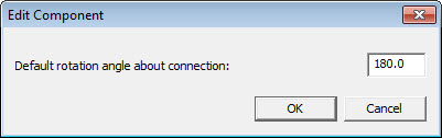
Edit Component dialog box
In the Default rotation angle about connection box, enter the angle (any angle from +180° to -180° inclusive). 0 (zero) is the default angle.
Click OK to rotate the component in the graphic area.
Click Save.
More:
Custom Probe Builder Utility Dialog Box
Custom Probe Builder Utility File Menu
Custom Probe Builder Utility CAD Components Tab