Creating QuickFeatures
About QuickFeatures
You can use the QuickFeatures functionality to create
Auto features from gestures.
These gestures are usually click or click-and-drag operations with key
combinations. You perform the gestures with the mouse on the CAD model
without any menu options or dialog boxes. Also, if models contain point
features, and PC-DMIS
is in Curve mode, you can use QuickFeatures to box-select and create multiple
point features at a time. For more information, see "Creating
Vector Point Features by Box-Selecting" below.
When you create QuickFeatures, dialog boxes with feature
lists (such as for constructions or dimensions) can remain open. As
you add the new features into the measurement routine, PC-DMIS adds them into the
feature list and automatically selects them for the current operation.
By default, when you create a feature from the QuickFeature
functionality and there is no other dialog box displayed, the measurement
strategy widget appears. This widget lets you change a feature's main
parameters. For more information, see "Using
the Measurement Strategy Widget" in the next main topic.
Requirements
Your CAD model can contain either surface data or wireframe
data. However, due to limitations in wireframe data, if your model is
a wireframe-only model, PC-DMIS
cannot create these features using the QuickFeature functionality:
Vector Point
Angle Point
Plane
Sphere
Also, QuickFeatures only function with contact Auto features.
General Process to Create QuickFeatures
You can choose to work with or without the Auto
Feature dialog box open. However, the procedure below assumes your
Auto Feature dialog box is not open. Also, the
measurement strategy widget does not appear if you use the Auto
Feature dialog box.
In the Edit window, click to define where to
insert the new feature.
In the Graphic Display window, position your
mouse pointer over the CAD element.
For point features (Vector, Edge, Angle, Corner),
press Ctrl + Shift and click on the CAD element to create the feature.
If you enable a 3D grid on the Graphic Display
window, the software snaps Vector, Edge, and Angle points to the nearest
intersection on the grid. For more information, see "Adding
a 3D Grid" in the "Editing
the CAD Display" chapter.
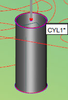
For Plane, Circle, Ellipse, Cylinder, Cone,
or Sphere, press Shift and click on the CAD element to create the
feature.
Example of a highlighted 3D Cylinder
For Line, Round Slot, Square Slot, Notch Slot,
and Polygon feature types, follow the instructions in their respective
topics below. These feature types, and other information not covered
in this general procedure, are discussed below.
By default, the measurement strategy widget
appears. You can use this widget to modify common feature properties.
For information on the measurement strategy widget, see "Using
the Measurement Strategy Widget" in this chapter.
Continue to create any other QuickFeatures
you need. With each new feature you create, PC-DMIS
automatically applies and accepts the previous feature. This also
works with multi-QuickFeatures
below.
Once you're done creating your features, click
the green Apply button to accept the final
feature and close the measurement strategy widget.
Creating Line
Features
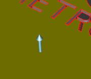
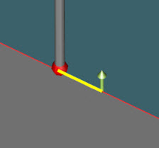
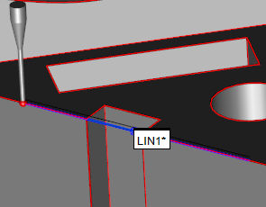
To create a basic line feature, position the
mouse pointer near a surface edge where the angle between the two
surfaces is 90 degrees. Press and hold the Shift key on your keyboard.
Click and drag the pointer for a short distance along the line. PC-DMIS starts to highlight
the line. An arrow representing the edge vector (green) appears.
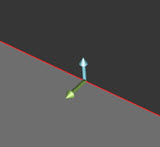
Drag to define the length
of the line and release the mouse button. PC-DMIS
places the line's start point where you click the button and the end point
where you release the button.
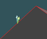
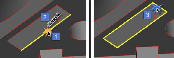
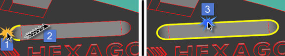
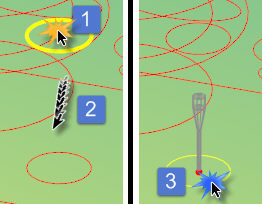
To create a line feature from multiple, colinear,
line elements, press and hold Shift, (1) hover the pointer over a
line, click and drag the pointer for a short distance along the line
to start to highlight it; then (2) move the pointer to another colinear
element and drag to define the length of the line. Once the software
highlights the elements and the line is the desired length, (3) release
the mouse button to create the line feature from the line elements.
Example of a line from two
colinear elements
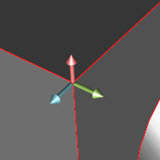
You can use the Swap Vectors
button on the QuickFeatures Widget to flip the edge vector of the line.
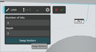
Example of the Swap Vectors button on the QuickFeatures
Widget
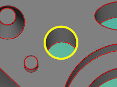
Creating Circle Features
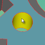
To create a basic circle feature, press and
hold the Shift key, then hover the pointer over the circle's arc.
Once it highlights the circle, click the circle to create the feature.
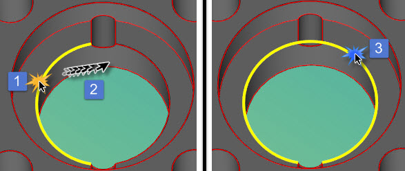
To create a circle feature from two disjointed
arcs:
Press and hold the Shift key, hover the
pointer over one arc, and then click to select the arc.
Move the pointer to the other arc to highlight
it.
Once the entire circle is highlighted,
release the mouse button to create the feature.
Creating
Circular Multi-QuickFeatures
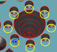
This procedure creates circular features (circles or
cylinders) of the same size, such as a bolt hole pattern:
To create multiple circular features:
Select one or more surfaces, and then press
and hold the Shift key.
Hover the pointer over one circular feature
to highlight all circular features of that diameter on those surfaces.
Once all the features are highlighted,
click the feature to create the highlighted circular features.

You can also create multiple circular features
from countersunk and counterbored holes. To do this, follow the instructions
in the preceding paragraph, but select the circular features just
below the surface.
The counterbore and countersink algorithm works
better with models that natively contain surface topology, such as
these model types:
ACIS
CATIAv5
CATIAv6
Creo
Inventor
JT
NX
Parasolid
Solid Edge
SolidWorks
STEP
IGES files do not work as well, because they do
not contain surface topology.
Multi-QuickFeatures work with up to 500 circular features
per surface. If you have a surface with more than 500 circular features,
Multi_QuickFeatures does nothing. In that case, you need to use the
box-select method to create the features. For information, see "Box Selecting
to Create Multiple Auto Features".
Creating Square Slot Features
Creating Round Slot Features
To create a round slot:
Press and hold Shift, and then hover the
pointer over one of the circular ends of the slot and click and
drag the pointer a short distance along the curve to highlight
it.
Move the pointer to a straight side.
Once the entire slot is highlighted, release
the mouse button to create the feature.
You can also start by hovering over a straight
side, click and drag the pointer a short distance to highlight it.
Then move the pointer to a circular end. Once the slot is highlighted,
release the mouse button to create the feature.
To create round slots that are on a non-planar
surface, repeat the above steps but hover the pointer over a cylindrical
end of the round slot instead of a circular edge.
Creating Notch Slot Features
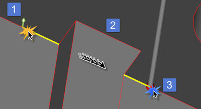
To create a notch slot:
Press and hold Shift, and then hover the pointer
over one of the legs of the notch.
Click and drag the pointer a short distance
along the leg to highlight it (1).
Move the pointer to an adjacent side (2).
Once the entire notch is highlighted, release
the mouse button (3).
Creating Polygon Features
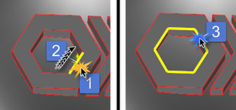
To create a polygon feature:
Press and hold Shift, and then hover the pointer
over one side of the polygon.
Click and drag the pointer a short distance
along the side to highlight it (1).
Move the pointer to an adjacent side (2).
Once the entire polygon is highlighted, release
the mouse button (3).
Creating Features from Wireframe Models
You can create any feature except those mentioned in
the "Requirements" heading above.
From the Graphic Modes toolbar, select Curve Mode  and then follow the instructions given in this topic to create the feature
as usual.
and then follow the instructions given in this topic to create the feature
as usual.
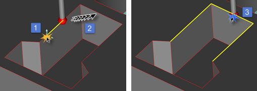
Cone and cylinder features require two circle elements
with coaxial centroids. For cone and cylinder features:
Press the Shift key and then hover the pointer
over one of the circles making up the feature (1).
Click to highlight that circle.
Move the pointer to highlight the feature's
other circle (2).
Once both elements are highlighted, release
the mouse button to create the cone or cylinder from the two circles
(3).
Cylinder Created from Wireframe Elements
Creating
Vector Point Features by Box-Selecting
If your CAD model has a lot of point features, you
can quickly create them by box-selecting them. For this to work, the CAD
model must already have the points defined as individual CAD elements.
Also, the part model must have surface data.
From the Graphic Modes
toolbar, select Curve Mode .
Press and hold Shift.
Click and drag a box around the point features.
Release the mouse button to create vector point
features from the selected point CAD elements.
Additional Information on QuickFeatures
You can select colinear or coplanar elements.
To do this, press and hold Shift, hover the pointer over a line or
plane, click and hold the mouse button, and move the pointer to a
colinear or coplanar element. Once all the elements are highlighted,
release the mouse button to create the feature from both elements.
For an example, see "Creating
Line Features" above.
You can toggle what features are executed within
the Graphic Display window. To do this, press Alt and click on the
feature label to toggle its marked state. For information on how to
mark features, see "Marking
Commands for Execution" in the "Editing
a Measurement Routine" chapter.
You can have PC-DMIS
automatically generate safe moves inside the QuickFeature. To do this,
select Operation | Graphic Display Window | Clearance
Move | Within feature prior to creating the features. If this
menu option is enabled, moves (between sample hits and among hits
in the same list) are automatically computed and drawn as lines.
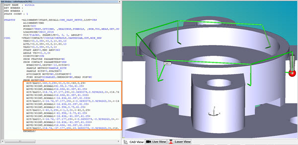
Example of Within Feature
set to active
For details on how to create
clearance moves, see "Inserting
Clearance Moves Automatically" in the "Inserting
Move Commands" chapter.
If you select Operation
| Graphic Display Window | Clearance Move | With Feature Creation,
PC-DMIS generates
clearance moves between QuickFeatures. The Auto
Feature dialog box must be closed.
Automatic safe moves between features that
use different probe tip angles is not supported. You must manually
define these moves.
PC-DMIS
automatically updates the contents of an open Auto
Feature dialog box. During feature creation, it retrieves the
data from the feature on the CAD model.
For a created feature, the
dialog box updates to the feature you selected.
For an edited feature, it
only does this if the selected feature matches the edited one.
In both cases, the default
values for the feature come from entries.
Related
Topics:
Using
the Measurement Strategy Widget

 Vector
Point
Vector
Point