For details on extracting Auto features from a Mesh, see the "Extracting Auto Features from a Mesh" topic in the PC-DMIS Laser documentation.
For details on extracting Auto features from a Pointcloud (COP), see the "Extracting Auto Features from Pointclouds" topic in the PC-DMIS Laser documentation.
You can construct an edge point that is extracted from a scanned pointcloud (COP) or Mesh.
Ensure that your measurement routine has a Pointcloud (COP) or Mesh command.
Access the Construct Point dialog box (Insert | Feature | Constructed | Point).
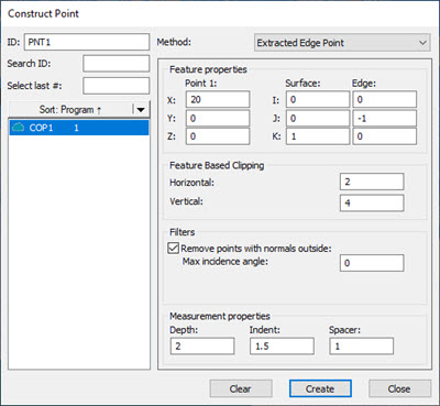
Construct Point dialog box - Extracted Edge Point
Select the Extracted Edge Point option from the Method list. This changes the Construct Point dialog box to show the options to create the extracted point.
From the Reference area, select the COP or Mesh.
Click on the CAD model or data to define the nominal (or from the Feature properties area, in the X, Y, and Z boxes, type the nominal location). A black line shows the current edge vector. The center of this line is the nominal location.
PC-DMIS draws the extraction zone and centers it around the XYZ location point. This box defines the extraction zone that PC-DMIS uses for the edge point extraction. The yellow rectangle is the surface. The yellow rectangle is the horizontal zone and the green rectangle is the vertical. The orange points are the candidate points that the extraction considers.
In the I, J, and K boxes, define the Surface and Edge vectors. The black line, the edge vector, needs to be in the same direction as your part's edge.
From the Feature Based Clipping area, define the Horizontal and Vertical values. This sets the dimensions for the green extraction zone region. Consider part variability when you define the extraction zone.
If you want to filter out any points that are outside of a maximum incidence angle, from the Filters area, select the Remove points with normals outside check box and type the value in the Max incidence angle box.
From the Measurement properties area, define the Depth at which you want to evaluate.
Use the Indent, and Spacer values to determine the plane and the edge. For information on these properties, see the "The Dialog Box Options" sub-topic below.
Click the Create button. Based on the parameters that you specified in the dialog box, PC-DMIS does an analysis of the candidate points, and returns (or extracts) the measured point and projects it to the surface.
PC-DMIS creates the command in the Edit window:
PNT1 =FEAT/POINT,CARTESIAN
THEO/location,edge_vec,surf_vec
ACTL/location2,edge_vec2,surf_vec2
DEPTH=n1,INDENT=n2,SPACER=n3,
HORIZONTAL CLIPPING=n4,VERTICAL CLIPPING=n5,
REMOVE POINTS WITH NORMALS OUTSIDE=tog1,n6
CONSTR/POINT,EXTRACTED_EDGE_POINT,ref_1
location - This stands for the XYZ nominal location.
edge_vec - This stands for the I, J, K edge vector.
surf_vec - This stands for the I,J,K surface vector.
location2, edge_vec2, surf_vec2 - These are the same as the items above but contain the actual measured values.
n1 through n6 - These numbers stand for the values for the different properties. n6 is visible only when tog1 is YES.
tog1 - This is either YES or NO based on the check box state.
ref_1 - This is the reference to the cloud of points (i.e. COP1).
For an example command, see the example below.
ID - Defines the extracted point feature's label.
Reference - Select the Pointcloud or Mesh object(s) from this list that PC-DMIS will use in the extraction.
Feature properties - This area defines the location for the point and the surface and edge vectors.
Point 1 - The X, Y, and Z boxes define the location of the point. PC-DMIS draws a black line for the edge vector in the Graphic Display window. The center of the black line is the point's location.
Surface - The I, J, and K boxes define the surface vector. PC-DMIS uses this vector along with the spacer value to calculate the surface. PC-DMIS draws the surface as a yellow plane in the Graphic Display window. When PC-DMIS creates the extracted point, it projects it to this surface.
Edge - The I, J, K boxes define the edge vector. PC-DMIS draws the edge vector as a black line in the Graphic Display window.
Measurement properties - This area defines properties that PC-DMIS uses to extract the point.
Depth - This defines the depth. PC-DMIS extracts the point from the considered points at this depth up to the edge. It then calculates the best point and projects it onto the plane. PC-DMIS shows an upside-down blue T to indicate the depth. One blue line extends down from the reference plane. Another blue line is drawn parallel to the black line at that depth. The Depth value must be within the Vertical value of the Feature Based Clipping area.
Indent - This defines how far from the edge to draw the center of the spacer. PC-DMIS shows a red line to indicate the indent distance.
Spacer - This defines the size of the circular area (a radius) that PC-DMIS uses to calculate the surface. PC-DMIS draws a purple circle to indicate the spacer.
Feature Based Clipping - This area defines the boundaries of the extraction zone. Consider part variability when you define the extraction zone.
Horizontal - This defines the width of the extraction zone (yellow rectangle).
Vertical - This defines the height of the extraction zone (green rectangle). If you type a Depth value larger than this value, PC-DMIS increases this value to match the depth.
Filters - This area provides a check box and an angle box to filter out points beyond a defined incidence angle. This is useful if you have thin parts, like sheet a metal part, and the extraction zone may include scan data on both sides of the part. You can use the Max incidence angle box to define an angle. If you mark the check box, PC-DMIS compares the estimated normal of each scanned point to the feature theoretical normal. Points that are beyond that angle are removed from consideration.
Suppose that you have a pointcloud scan of the Hexagon demo block named COP1, and you have these values in the Construct Point dialog box:
The result in the Graphic Display window while the dialog box is open, is this:


Example Constructed Edge Point - Zoomed Out (left) and Zoomed In and Rotated (right)
Here's a view without the orange candidate points to provide a more visible example:
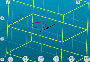
The green box defines the extraction zone. The yellow plane defines the surface.
The black line matches the edge vector.
The center of the black line, the black dot, indicates the center location of the cube. This dot appears once you create the point. This is defined from the XYZ location.
The red line shows the indent. In the above picture, you can see that it extends from the edge in the Y plus direction. This defines the spacer's distance from the edge.
The purple ellipse shows the spacer.
The blue line shows the depth.
When you click Create, PC-DMIS adds this point in the Edit window:
PNT1       =FEAT/POINT,CARTESIAN
            THEO/<20,0,0>,<0,-1,0>,<0,0,1>
            ACTL/<20,-0.064,0.054>,<0.0000197,-1,0.0002969>,<0.0042823,0.000297,0.9999908>
            DEPTH=2,INDENT=1.5,SPACER=1,
            HORIZONTAL CLIPPING=2,VERTICAL CLIPPING=4,
            REMOVE POINTS WITH NORMALS OUTSIDE=YES,0
            CONSTR/POINT,EXTRACTED_EDGE_POINT,COP1