The Insert | Feature | Read Point inserts a point in the Edit window at the read in position. This tells PC-DMIS to read the probe's current position.
The following syntax illustrates what's inserted into the Edit window.
ID =FEAT/ POINT, TOG1
THEO / x, y, z, i, j, k
ACTL / x, y, z, i, j, k
READPOINT/
READPOINT - Identifies this feature as a read point created from the probe's position.
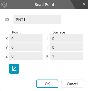
If you press F9 on this command, PC-DMIS displays the Read Point dialog box.
Read Point dialog box
ID - This box displays the Feature ID.
Point (X, Y, Z) - This box displays the X, Y, Z location for the constructed point.
Surface (I, J, K) - This box displays the I, J, K approach vector of the probe.
 - The Cartesian/Polar
icon switches the display of the X, Y, and Z values between the Cartesian
and Polar coordinate systems. The XYZ labels
display RAH when you switch to Polar.
- The Cartesian/Polar
icon switches the display of the X, Y, and Z values between the Cartesian
and Polar coordinate systems. The XYZ labels
display RAH when you switch to Polar.
PNT1 =FEAT/POINT,CARTESIAN
THEO/<7.4982,2.0111,0.95>,<0,0,1>
ACTL/<7.4982,2.0111,0.95>,<0,0,1>
READPOINT/
If you execute this type of point feature in Offline mode, and the feature follows a MODE/MANUAL command, the software copies the theoretical vector and position to the measured vector and position; otherwise, the value comes from the current probe position.