An alignment consists of two transforms:
Machine origin to Part origin (termed "Machine-to-Part")
CAD origin to Part origin (termed "CAD-to-Part")
If you modify either of the transforms, PC-DMIS displays a Yes/No message similar to the following, letting you choose how the commands dependent on the alignment are updated:
PC-DMIS:
External alignment file FIXTURE1 has changed! Update dependent command (Moves, Feature THEO, ACTL, and TARG values)?
Choose 'Yes' to convert the dependent commands to the new alignment coordinate system.
Choose 'No' to leave the dependent commands unchanged.
Yes/No message asking if PC-DMIS should update dependent commands
You can choose to convert the dependent commands to the new alignment coordinate system or to leave the dependent commands unchanged.
The text in the message indicates what types of commands and command values the software updates for each alignment change.
Different commands and command values may change depending on the transform change. This table lists the commands and command values that are updated after a transform change:
Commands and command values that may update after a changed transform: |
Transform Change |
||
Machine-to-Part |
Cad-to-Part |
Both |
|
|
|
|
|
In the following two general scenarios, you need to decide how to update the commands in the measurement routine in response to an alignment change:
When you load a measurement routine that recalls an external alignment file. See "Updating Commands When Loading a Measurement Routine " below.
When you add a new alignment or modify or delete an existing alignment while in Learn mode. See "Updating Commands While in Learn Mode" below.
Updating Commands When Loading a Measurement Routine
A measurement routine that includes RECALL/ALIGNMENT, EXTERNAL commands attempts to re-load the referenced external alignment files each time the measurement routine opens.
The correct answer to the question "Update dependent commands?" depends on why the external alignment file has changed. Consider these reasons:
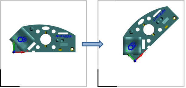
The Alignment file changed because you moved the part on the CMM - In this case, the theoretical and actual values of the commands dependent on that alignment need to remain fixed, relative to the part (see the figure below). The Machine-to-Part transform is modified. It’s possible that the Cad-to-Part transform is also modified, but that is not very common. Choose No at the Yes/No message so the values of the dependent commands do not change. The position and orientation of the part can then change while retaining the previous dimensional information, similar to equating an alignment. This is the most common scenario.
Part Moved on CMM
The Alignment file changed because you made small adjustments to the alignment to see how it affects the measured results, without actually re-measuring the part - In this case, the values of the dependent commands must be updated to the new alignment coordinate system. The Machine-to-Part transform is modified, but the Cad-to-Part transform has not changed.
This usually requires the SAVE/ALIGNMENT command be configured to only include the Machine-to-Part transform, not both transforms.
Choose Yes at the Yes/No message.
The Alignment file changed because you moved the alignment origin to a new location on the part, but you did not move the part itself - For example, you changed the level, rotate, and/or locate features to different features. In this case, theoretical and actual values of the commands dependent on that alignment must be updated to the new alignment coordinate system. The Cad-to-Part transform has been modified, but the Machine-to-Part transform has not changed.
This requires the SAVE/ALIGNMENT command to be configured to include both transforms.
Choose Yes at the Yes/No message so that the measured data does not shift away from the CAD geometry. This is not a common scenario.
When loading a measurement routine that recalls an external alignment, if the external alignment file transforms have been modified since the measurement routine was last saved, by default, PC-DMIS does not display the dialog box, asking to update the dependent commands. Instead, it automatically answers No to that question. You can control this behavior with the UpdateExtAlignmentDepCommandsDuringFileOpen entry. For information on how to modify values for entries, see "Modifying Setting Entries".
Updating Commands While in Learn Mode
When you edit a measurement routine in Learn mode, if changes are made that modify or delete an existing alignment command or create a new one, PC-DMIS asks if you want to update the commands dependent on that alignment.
The correct answer to the question "Update dependent commands?" depends on why the alignment definition has changed. Consider these reasons:
The alignment definition changed because you moved the alignment command origin to a new location on the part - For example, you changed the level, rotate, and/or locate features to different features. In this case, the theoretical and actual values of the commands dependent on that alignment command need to be updated to the new alignment coordinate system (see the figure below). Both transforms have been modified.
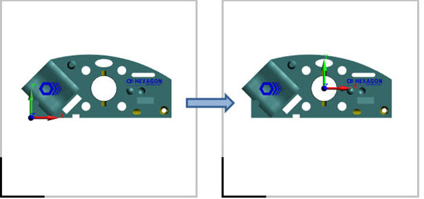
Alignment moved on part
Choose Yes at the Yes/No message so that the measured data does not shift away from the CAD geometry. This is a common scenario.
The alignment is from a command that recalls an external alignment (RECALL/ALIGNMENT, EXTERNAL), and you changed the file reference to a different external alignment file that represents the part at a different location on the CMM - In this case, the theoretical and actual values of the commands dependent on the alignment remain fixed relative to the part. The Machine-to-Part transform has been modified, but the Cad-to-Part transform needs to remain the same.
Choose No at the Yes/No message so that the values of the dependent commands are not changed. This is a less-common scenario. It allows the position and orientation of the part to change while retaining the previous dimensional information, similar to equating an alignment.