Looking for Geometric Tolerance commands? If so, see:

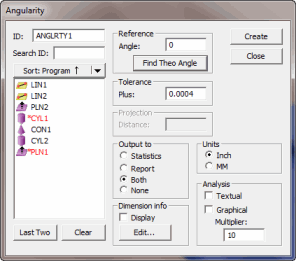
Dimension Angularity dialog box
The Insert | Dimension | Angularity menu option computes the angularity error of a plane or line to a datum plane or line. (If only one feature is selected or entered, PC-DMIS uses the current workplane as the datum.)
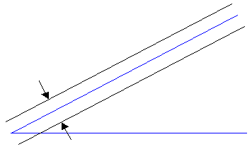
Similar to perpendicularity or parallelism, the Angularity dimension allows you to specify an angle that isn't 90 degrees (perpendicularity) or 0 degrees (parallelism). For example, if you specify a 45-degree angle, PC-DMIS creates a tolerance band at 45 degrees and checks that the hits are within that tolerance band.

The measured value is an angle (blue). The angularity's tolerance band is two parallel lines or planes (black) that never meet.
More:
To Compute the Angularity Error by Using the ANGULARITY Option: