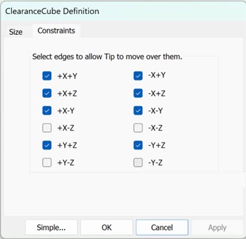
Use the Constraints tab to specify which of the 12 edges you want to allow the tip to move over. If you do not select an edge, PC-DMIS does not move the tip.

ClearanceCube Definition dialog box - Constraints tab
If an edge is cleared, PC-DMIS does not move the tip over that edge. You can use constraints to restrict tip movement to avoid collision with the clamps.
The Graphic Display window displays those edges in blue on the ClearanceCube. If none of the four edges of a face are selected, PC-DMIS displays that face in bright yellow.
Clear Edges Using the CAD Model
You can select or deselect an edge that you want or not want to pass over using the CAD in the Graphic Display window. To do this, with the ClearanceCube Definition dialog box displayed, click an edge on the CAD in the Graphic Display window. You can see as you select or deselect the edge on the CAD model, PC-DMIS selects or deselects that same edge.
You can also rotate the CAD model with this dialog box open. To do this, press the Ctrl button and right-click and then move your mouse cursor to the desired rotation position.
ClearanceCube Settings for Feature or Moveset Command
You must set ClearanceCube motion for every feature in a measurement routine.
PC-DMIS moves the tip to the starting face set for a feature before the measurement of the feature.
PC-DMIS moves the tip to the ending face set for a feature after the measurement of the feature.
PC-DMIS does not execute ClearanceCube moves if it is set off for a feature.
ClearanceCube Settings for Tip Command
You can activate ClearanceCube motion for tip commands.
If the tip change completes safely in front of the part face, set the ClearanceCube motion for the TIP command to the Off condition. You must ensure that the last position of the tip is safe for rotation or change.
If ClearanceCube motion is activated for the TIP command, PC-DMIS needs to move the tip to a safe location. The tip must be located on the face of or outside of the ClearanceCube.
This can be accomplished by either:
Setting ClearanceCube motion to the ending face of the last feature
Or,
Adding a Moveset command and setting the ClearanceCube motion to the ending face
PC-DMIS displays the message during execution of a measurement routine if the ClearanceCube is activated for the TIP command and located inside the ClearanceCube.
ClearanceCube Settings for Scan Command
The Advance Scans are containers for BASICSCAN commands. You can set ClearanceCube motion for a scan and each BASICSCAN in a scan.

Example Basicscan command in a scan
PC-DMIS executes the scan and the Basic scan in this way:
PC-DMIS moves the ClearanceCube based on the starting
face of the scan (SCN1).
PC-DMIS executes the Auto Move before scanning as defined in the scan command.
PC-DMIS moves the ClearanceCube
based on the starting face of the Basic scan (SCN1.1).
PC-DMIS scans the Basic scan (SCN1.1).
PC-DMIS moves the ClearanceCube based on the ending face of the Basic scan
(SCN1.1).
PC-DMIS repeats these Basic scan SCN1.1 steps for SCN1.2 through SCN1.n.
PC-DMIS executes the Auto Move after scanning as defined
in the scan command (SCN1).
PC-DMIS moves the ClearanceCube based on the ending face of the scan (SCN1).
Tip Moves Using Constrained Edges
Tip has activated ClearanceCube Moves set to ON
When you define constraints for some feature edges, PC-DMIS does not allow the tip to cross those edges. PC-DMIS does allow the tip to move freely at the T1A0B0 rotation height. Because of this, you must use a shorter fixture and clamp configuration for your part than this height. In some cases, you may have to use a MOVESET command to move the tip to the desired location.
If all four edges of a ClearanceCube face are constrained, PC-DMIS shows the edges in a light blue color in the Graphic Display window. PC-DMIS does not allow you to use this face for ClearanceCube motion.
Tip has activated ClearanceCube Moves set to OFF
When the TIP command becomes active with ClearanceCube move set to OFF, you must ensure that the tip crosses the correct edges and only edges that are not constrained. You may have to use MOVESET commands to achieve the correct path for the tip's motion.