In this step, you will perform a more accurate calibration to define the alignment of the axes between arm 1 and arm 2.
Swap out the TP2 tip on the arm 1 extension with a 15 mm tip.
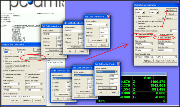
In the Multiple Arm Calibration dialog box (Operation | Calibrate/Edit | Multiple Arm Mode), make sure the following are set:
For First arm probe, select the PROBALL probe.
For Second arm probe, select the PROBE2 probe.
For Number of spheres to measure, define how many spheres PC-DMIS will measure with each arm. For this example we'll use a value of 6. But for your machine, you may want to choose a different number based on the dimensions of your machine. A value of 9 is good. 12 is the maximum. The higher the number, the greater the accuracy, but you'll also experience an increase in calibration time with more spheres during the DCC calibration.
Calculate the orientation plane so that the sphere of arm 1 will move on a plane lying on the Y center line of the machine. This will allow arm 2 to later reach the ball in all positions. To do this:
Manually move arm 1 to the six sphere positions specified in the Multiple Arm Calibration dialog box.
From the Multiple Arm Calibration dialog box, click Edit Positions and correct each sphere position as needed to improve the distribution. This may be needed since the positions are not perfectly aligned nor evenly distributed on the vertical plane.
You may find it helpful to read the position of the active arm to fill in the X, Y, Z coordinates. The Read Position button automatically uses the current X, Y, Z position of the arm.
Choose the Orientation and Origin option.
Choose the DCC calibration option.
Click Calibrate. The armarm.dat file is regenerated with a more accurate mapping from this calibration.
Dialog boxes showing the settings used
The next step provides information on performing the DCC calibrations.