 ISO
14405-1 : Nominal with Deviations
ISO
14405-1 : Nominal with Deviations ISO
14405-1 : Nominal with Deviations
ISO
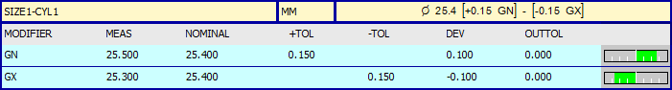
14405-1 : Nominal with DeviationsWith the NOMINAL_WITH_DEVIATIONS mode, PC-DMIS compares the upper specification operator measured size against the upper limit of size. It also compares the lower specification operator measured size against the lower limit of size. Therefore, the Size command generates two measured values for a given feature of size:
ISO
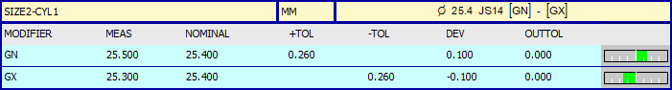
14405-1 : Tolerance CodesWith the TOLERANCE_CODE mode, the PC-DMIS report mimics NOMINAL_WITH_DEVIATIONS mode, except that it displays the tolerance code in the dimension header:
ISO
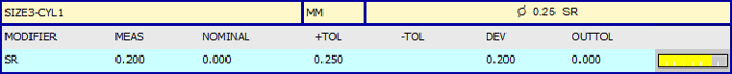
14405-1 Range of SizesWith the RANGE_OF_SIZES mode, PC-DMIS compares a maximum measured size against a minimum measured size and reports the difference. This mode requires a single measured value. The software compares that measured value against an upper tolerance.
ASME
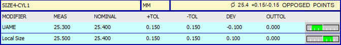
Y14.5 - Local SizeWith ASME Y14.5, two size characteristics are reported, the Unrelated Actual Mating Envelope (UAME) and Local Size.
The UAME is the minimum circumscribed size for external features (e.g. pin) and the maximum inscribed size for internal features (e.g. hole).
Local Size:
Circular Elements (default) report the smallest circumscribed circular element (internal feature/ hole) or largest inscribed circular element (external feature/pin) amongst all local sizes.
Opposed Points reports the largest opposed point distance (internal feature/hole) and smallest opposed point distant (external feature/pin) amongst all local sizes.
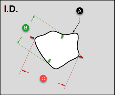
ASME Y14.5 Local Size Example
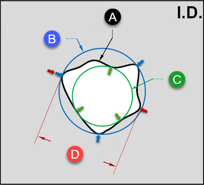
True shape of the feature's cross section
Local Size (Circular Elements) - Æ 44.2659
UAME - Æ 43.8849
Local Size (Opposed Points) - Æ 44.2656
The symbol "Æ" denotes Diameter.
For an inner diameter (ID) feature using the ASME Y14.5 standard, you can see from the above image that:
The Unrelated Actual Mating Envelope (UAME) is the largest possible inscribed circle.
The Local Size is based on which option you select from the Local Size options list of the Geometric Tolerance Size dialog box (see descriptions above).
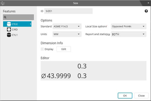
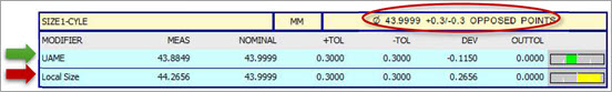
If you select Opposed Points from the Local Size options list as shown in the Geometric Tolerance Size dialog box image above, PC-DMIS reports the result as:
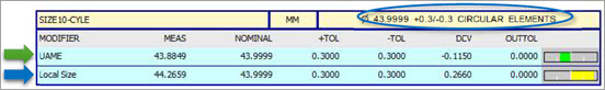
If you select the Circular Elements option, PC-DMIS reports the feature as:
In all cases where details related to the ASME standards are concerned, you should consult the primary source at The American Society of Mechanical Engineers (ASME) website.
When PC-DMIS reports Size using the ISO standard, it is based on Local Size only. Because of the Independency Rule, it is not based on the unrelated or related mating envelope. For details on the ISO Independency Rule, see ISO 8015: 2011 section 5.5 “Principle of Independence”.
True shape of the feature's cross section
Minimum Local 2-Point Size
Maximum Local 2-Point Size
For example, when you measure a cylinder feature at multiple levels, PC-DMIS evaluates each cross section individually and then reports the Maximum and Minimum 2-point size, similar to performing a caliper check.
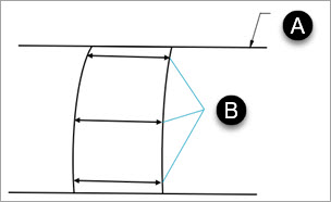
Datum feature simulator of datum feature A (Plane)
Actual local sizes (Any individual distance at any cross section of a feature of size)
In all cases where details related to the ISO 1101 standards are concerned, you should consult the primary source at The International Organization for Standardization (ISO) website.