You can use the options in the General feature parameters group to define the general parameters for a Point feature. The available options depend on the type that you select in the Type of measurement area:
tactile - The feature is not extracted from the COP.
optical - The feature is extracted from the COP.
The following graphics show the options for each feature.
AA Feature
Tactile measurement options:

Optical measurement options:

AC Feature
Tactile measurement options:

Optical measurement options:

Descriptions
The following table describes the options.
For descriptions of the icons that appear in this group, see "Using the Icons".
Item |
Description |
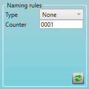
Naming Rules area |
Type list: Select the type of naming rule:
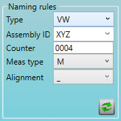
Counter box: Type an integer value for the feature counter. The maximum value is four digits. The Counter box is available for all three Type options, and it is the only option when you select None from the Type list. PC-DMIS increments the Counter value by one each time you create a feature. The following options appear when you select the VW type:
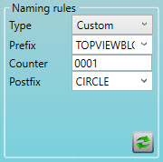
These options replace the Alignment list when you select N from the Meas type list: Position 10 list: Select the vehicle coordinate system for the VW naming rule. Position 12 list: Select the alignment area for the VW naming rule. Select the alignment area for the VW naming rule: These options appear when you select the Custom type:
|
Other area |
Set list: Select the name of the group of elements. Thickness box: Type the thickness to be applied as an actual value to the surface or edge values of the feature. Thickness toggle list: Select the thickness toggle:
Safe distance list: Type or select the distance move before and after the measurement. Avoidance move list: Select when to apply an avoidance move:
Symmetrical check box: If this element also exists on the other side of the car, select this check box. |
Shank measurement area |
Select the type of shank measurement:
Immersion depth box: Type the offset of the measured point along the shank direction. |
Relative measurement area |
Off option: Select this option if you do not want to use relative measurement. Single option: Select this option to measure a single feature from the XYZ list. The list appears when you select Single:
Relative measurement area with Single option Multiple option: Select this option to measure multiple features (one for each axis) from the X, Y, and Z lists. These lists appear when you select Multiple:
Relative measurement area with Multiple option |
Optical parameter area |
Pointcloud list: Select the pointcloud from which you want to extract the feature. Diameter box: ESF constructs a sphere with this diameter around the nominal position and filters out any points that are outside of this sphere. Max. deviation box: Type the maximum deviation between two points in the COP. If two points have a higher deviation, the extraction fails. Max. distance box: Type the maximum distance between two points in the COP. If two points have a higher deviation, the extraction fails. Avg. distance box: Type the average distance between two points in the COP. If the average distance is higher, the extraction fails. Force computation check box: If you select this check box, ESF tries to extract the feature even if you do not complete the other parameters in this area. |
More: