
Auto Sphere button
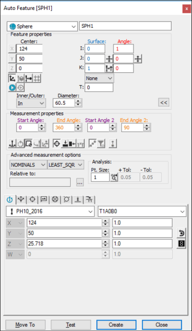
The Sphere sheet metal option allows you to define a sphere measurement. This measurement type is particularly useful when the sphere lies in a specific plane that is not parallel with any of the workplanes. The minimum number of hits needed to measure an auto sphere is four.
To access the Sphere option, access the Auto Feature dialog box for a sphere (Insert | Feature | Auto | Sphere).

Auto Feature dialog box - Sphere
With the dialog box open, use one of these methods to create the feature:
Using Surface Data on the Screen
To generate a sphere using surface data:
From the Graphic Modes
toolbar, click the Surface Mode icon ( ).
).
Click on a sphere in the Graphic Display window.
The dialog box displays the value of the selected sphere and vector once the points have been indicated.
Using Surface Data with the CMM
To generate a sphere using surface data with the CMM, touch the sphere in four locations using the probe. If additional mouse clicks are detected before you select the Create button, PC-DMIS finds the best sphere near the measured points.
You should select the Find Noms option in the Mode list for this measurement method. For more information on nominals, see the "Mode List" topic in the PC-DMIS Core documentation.
Using Wireframe Data on the Screen
To generate a sphere using wireframe CAD data:
Select the sphere to be measured. PC-DMIS highlights the selected sphere if it is available. (If another feature is selected, try to take two additional hits.)
Verify that the correct feature has been selected.
The dialog box displays the value of the selected DCC sphere and the vector once the sphere has been indicated.
Use this method to type the desired X, Y, Z, I, J, and K values for the sphere.
Type the desired X, Y, Z, I, J, and K values for the feature into the dialog box.
Click Create to insert the feature into your measurement routine.