Calibrating your probe tips tells PC-DMIS the location and diameter of your probe tips. You cannot execute your measurement routine and measure your part until you calibrate the probe tips. The terms "calibrate" and "qualify" are used interchangeably.
To begin the calibration process:
Make sure the Active tip list in the Probe Utilities dialog box (Insert | Hardware Definition | Probe) has the desired tip angles.
Select the probe tip or tips that you want to calibrate from the list.
Click Measure to display the Measure Probe dialog box.
If you have a probe changer and the currently active probe file is not the probe configuration in the probe head, PC-DMIS automatically drops off the currently loaded probe configuration and picks up the needed one.
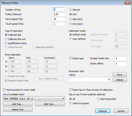
Measure Probe dialog box
The Measure Probe dialog box displays settings that apply to measurement for the purpose of probe qualification. Once you make the desired selections, click Measure to begin.
Requirements Prior to Calibration
To begin the calibrating process, you must define a qualification tool. The type of measurement(s) to be made on the tool depends on the type of tool (typically a SPHERE) and the type of tip (BALL, DISK, TAPER, SHANK, OPTICAL).
To select a currently-defined qualification tool from the list, click List of available tools.
To define a new qualification tool to add to the available tools listing, click Add Tool.
To change the configuration of the currently-defined qualification tool, click Edit Tool.
To delete the currently-defined qualification tool, click Delete Tool.
Once Calibration Starts
PC-DMIS displays one of two styles of messages that ask if the qualifying tool has been moved. The type depends on your machine's ability to use DCC hits to locate the qualification tool:
YES/NO Message Box
This message box appears for machines that do not support the ability to locate the qualification tool using DCC hits (such as manual-only machines):
Has the qualification tool been moved or has the machine zero point changed? WARNING: Tip is about to rotate to TIP1!
Yes No
Qualification Tool Moved Dialog Box
The Qualification Tool Moved dialog box appears if your measuring machine and probe configuration support the ability to locate the qualification tool using DCC hits:
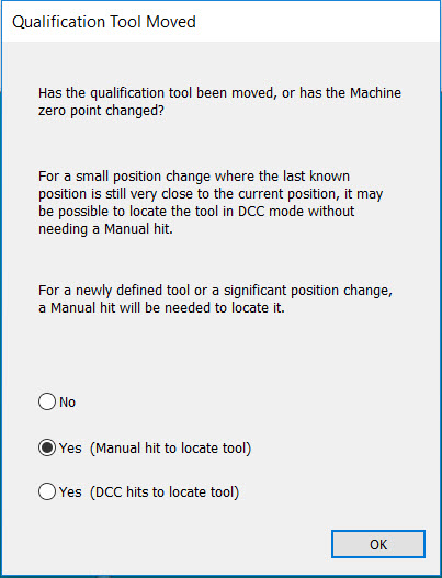
Qualification Tool Moved dialog box
If you select No, PC-DMIS displays the Execution dialog box. It does not require any manual hits unless they are appropriate for the selected measurement method (such as operating in Manual mode).
For a tactile probe on a Bridge-type CMM, PC-DMIS will continue with the automatic calibration routine.
If you select Yes (Manual hit to locate tool), PC-DMIS displays the Execution dialog box. It requires you to take one or more hits in Manual mode (depending on the tool type) before it continues the calibration process.
For a tactile probe on a Bridge-type CMM, you have to manually hit the sphere to locate the tool position.
If you select Yes (DCC hits to locate tool), PC-DMIS displays the Execution dialog box and automatically attempts to use DCC hits to locate the qualification tool. You may use this option when you have repositioned the qualification tool to nearly the same previous location.
About the Leg Collision Check for a Bridge CMM During Calibration
At this point, for a tactile probe on a Bridge-type CMM, PC-DMIS displays the Collision Check dialog box. It asks if you want to run the Leg Collision check:
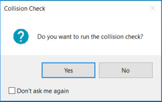
Collision Check dialog box - collision check message
If you select No, PC-DMIS continues with the standard calibration routine (it does not perform the Leg Collision check).
If you answer Yes, PC-DMIS verifies any collisions with the current limits in the CMM Limits area of the Part/Machine tab in the Setup Options dialog box. If necessary, PC-DMIS adds any safety movements. PC-DMIS displays the Collision Check dialog box with the name of the tip that it is currently checking:
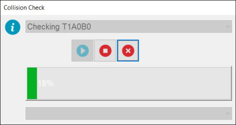
Collision Check dialog box - name of tip
The Leg Collision check takes a few seconds to run. The time depends on the number of tips selected. You can use the Stop or Cancel button to stop or cancel the check. If needed, PC-DMIS adds safety movements (retracting the tip along X or Y ) to avoid possible collisions with the CMM legs, and safety movements in Z to avoid possible collisions with the plate, roof, or gauge sphere.
After PC-DMIS runs the Leg Collision check, it executes the calibration routine which was improved with the safety movements, if needed.
In a few situations, the Legs Collision check may find some probe tip rotations that cause collisions that it cannot automatically resolve. In these cases, the calibration cannot safely execute, and PC-DMIS interrupts the calibration. It shows a "Can't calibrate" message and lists those problem tip names.
The Legs Collision check is available only when you run the calibration routine directly with the PC-DMIS interface. It does not work with Automation functionality or the AUTOCALIBRATE command.
Once Measurement Finishes
Once the measurement finishes, PC-DMIS calculates the qualification results as appropriate for the type of probe, tool used, and operation requested. The difference between the two Yes options in the Qualification Tool Moved dialog box only affects whether or not a manual hit is needed during measurement. For purposes of the post-measurement calculations, both Yes options are equivalent.
Following calibration, a brief summary for each tip is visible in the Active Tip List in the Probe Utilities dialog box. To see detailed results of the calibration, click Results in that dialog box.
Recalibrating
In general, PC-DMIS cannot tell if a probe tip needs to be recalibrated. Be sure to perform a recalibration if anything changes with your probe.
More:
Reset Tips to Theo at Start of Calibration