Once you are done measuring features, it's always a good idea to move the probe to a safe location above and away from the part on the table.
This step adds in two move point commands. One to move the probe further away from the part and a second to move the probe to a safe location for future executions or measurement routines.
From the Edit window, make sure the cursor is at the end of the CYL3 feature.
Select Insert | Move | Move Point to open the Move Point dialog box.
If the Move Point dialog box does not appear, PC-DMIS likely already inserted a MOVE/POINT command into the Edit window at the current probe location. In that case, click on the command and press F9.
From the Move Point dialog box, or directly in the Edit window define the X, Y, and Z values to define the move point location. Use these recommended values:
X of 25
Y of -100
Z of -25
Create a second MOVE/POINT command to bring the tip high up above the part at these recommended values:
X of 0
Y of -50
Z of 250
Here are some other ways you can insert a MOVE/POINT command.
Press Ctrl + M.
With your jog box, move the probe to a desired location, then from the Move Point dialog box press Read Pos. (On some jog boxes, you can press the PRINT button to insert the command.)
For more information on Move Points, see the "Inserting a Move Point Command" topic in the "Inserting Move Commands" chapter of the PC-DMIS Core documentation.
From the Edit window, cut and paste the CYL3 feature command so that it's after the third MOVE/POINT command.
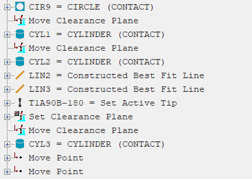
Choose View | Summary Mode, to put the Edit window in Summary mode. Then check your work. The last part of your Edit window from CIR9 down, should look like this:
Choose View | Command Mode to return the Edit window to Command mode.
If you need to make adjustments, you can modify values directly in the Edit window and even drag cut and paste commands to different locations. You can also press F9 on most commands to access a dialog box to change values there.
Go to the next step: "Calculate Dimensions"