Step 3 - Define the Ports
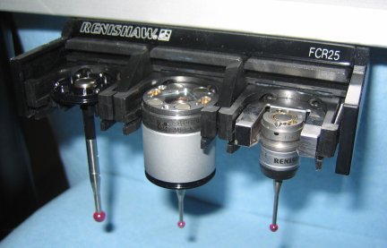
The example described below has a PA25-SH insert in port 1(left), NO INSERT in port 2 (middle), and a PA25-20 insert in port 3 (right).
To define the ports of your FCR25 Probe Changer:
Select the Ports tab in the Probe Changer dialog box (Edit | Preferences | Probe Changer).
In the Active probe changer list, select TYPE=FCR25.
In the Number of ports box, in multiples of three, specify the number of ports your FCR25 Probe Changer is to have. PC-DMIS then lists the specified number of ports as "ports" (for example, port 1, port 2, port 3, and so forth). Until you define the ports, these "port" entries display as "UNDEFINED". You must define all of the ports in the rack before you start.

Ports tab with undefined ports
Select a port from the list, and click Edit Port Data. The Probe Changer Port Data dialog box appears.
In the Port type list, select NO INSERT, PA25-SH, or PA25-20.
You may specify the XYZ values for the center position of the port or leave those values empty. In any case, PC-DMIS automatically populates these values upon successful calibration. See "Step 9 - Review Calibration Results".
To save the changes to the port data, click OK.
Repeat steps 4 through 6 for all ports in your changer.
Ports tab
To save your changes, click Apply.
The next step prepares you to calibrate the probe changer.