Step 6 - Measure Port 1/PA25-SH Insert
For the FCR25 Probe Changer, PC-DMIS prompts you through the process of measuring port 1 (the left-most port) through a series of message boxes. Follow the prompts and take the needed hits as shown in the pictures for each hit.
Hit 1 on top surface:
Please take a hit on the top face of the front left corner for port 1 (which is local port 1 on FCR25 unit number 1).
Use your machine's jog box to measure the first hit on the top surface of port 1 as shown in the image below:
![]()
First hit on the top surface of port 1
When you click OK, you are prompted to take the hit with the Execution dialog box.
Hit 2 on the front surface:
Please take a hit on the front face of the front left corner for port 1 (which is local port 1 on FCR25 unit number 1).
Use your machine's jog box to measure the second hit on the front surface of port 1, as shown in the image below:
![]()
Second hit on the front surface of port 1
When you click OK, you are prompted to take the hit with the Execution dialog box.
Hit 3 on the inside surface:
Please take a hit on the inside face of the front left corner for port 1 (which is local port 1 on FCR25 unit number 1).
Use your machine's jog box to measure the third hit on the inside surface of port 1 as shown in the image below:
![]()
Third hit on the inside surface of port 1
When you click OK, you are prompted to take the hit with the Execution dialog box.
This set of three hits establishes the location for the tool changer. These three hits would be the same if the port didn't have an insert. If you used a PA25-20 insert in this port, the hits would be taken on the insert in a similar fashion.
You are then asked to complete a few steps through the following message box:
Please do the following steps in the indicated order.
1. Remove the current SH-1/2/3 stylus.
2. Attach the SHSP (Stylus Holder Setting Piece).
3. Jog the probe to a safe location with a clear line of approach to the port(s) being calibrated.
4. Then click OK.
After you click OK the machine will begin DCC measurement.
Complete the instructions in the message box:
Remove the specified stylus (in this case, the SH-1/2/3 stylus).
Attach the SHSP as shown in the image below:
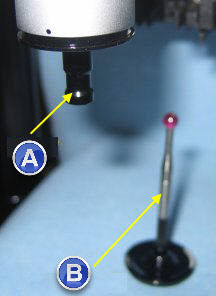
WARNING: When you do this, the machine moves. To avoid injury, stay clear of the machine. To avoid hardware damage, run the machine at a slower speed.
Attach the SHSP
(A) - SHSP
(B) - SH-1/2/3
Whenever the instructions direct that you should jog the probe to a "safe location" or a location "with a clear line of approach", you should move the probe to a position that is in front of and slightly above the rack.
When you have completed these steps, click OK to begin DCC measurement.
WARNING: When you do this, the machine moves. To avoid injury, stay clear of the machine. To avoid hardware damage, run the machine at a slower speed.
PC-DMIS automatically measures the three hits with the SHSP that were previously taken with the SH-1/2/3 stylus.
It also takes a hit on the opposite inside face.
This completes the measurement of port 1.
In the next step, you measure port 3.