Step 7 - Measure Port 3 / PA25-20 Insert
Before PC-DMIS can measure port 3 (the right-most port) for the FCR25 Probe Changer, you must first change the probe to the probe file you specified for the Second Probe File in step 5.
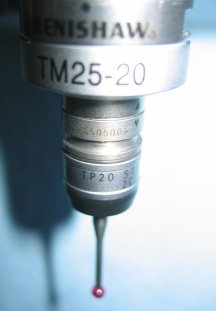
When prompted, remove the current module, and add the TM25-20 module to the end of the probe body. The image below shows the TM25-20 module and TP20 type stylus after this change:
TM25-20 module and TP20 type stylus
Changing probes may not be necessary depending on your FCR25 Probe Changer configuration. For example, if there are no inserts in any of the ports, then this probe change may not be necessary. The change specified in this step is only required to accommodate the calibration of port 3 with the PA25-20 insert.
After you change the probe, click OK. PC-DMIS displays the following prompt:
Please jog the probe to a safe location with a clear line of approach to the port(s) being calibrated, then click OK.
When you click OK the machine will begin DCC operation.
After you move the probe to a safe location, click OK to begin DCC measurement of the insert in port 3.
WARNING: When you do this, the machine moves. To avoid injury, stay clear of the machine. To avoid hardware damage, run the machine at a slower speed.
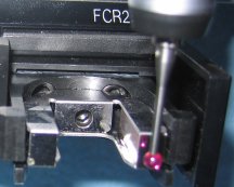
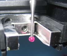
The following images show the probe taking measurements. PC-DMIS automatically takes hits to determine the location of the insert.
|
|
In the next step, you measure port 2.