Step 8 - Measure Port 2 / No Insert
Before you measure port 2 for the FCR25 Probe Changer, you are prompted to remove the module that was used for the measurement of port 3:
Please remove the module from the probe body, jog to a clear location and then click OK.
When you click OK the machine will begin DCC operation to move the probe body to a position above port 2.
Once you have removed the module and moved the probe to a safe location, click OK to continue the process.
WARNING: When you do this, the machine moves. To avoid injury, stay clear of the machine. To avoid hardware damage, run the machine at a slower speed.
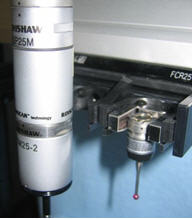
PC-DMIS moves the probe body to a position that is centered above port 2 as shown in the image below. (The image also shows the module that PC-DMIS expects you to add in the next prompt.)
Position centered above port 2
The procedure for measuring port 2 would be used for all ports if you didn't have an insert in any of the ports. The ports would also be measured in a different order (port 1 first, followed by port 2, and then port 3).
Place the desired module into the port and slowly lower the probe body towards the module while being careful not to collide with the port.
Continue lowering until the module jumps upwards slightly due to the magnetic attraction. Observe to see if the module jumps straight up (indicates good alignment) or tilts (indicates poor alignment).
Reposition and repeat as necessary until satisfied with the alignment, then click OK.
Follow the prompt to place the module into the port. Then, slowly lower the probe body towards the module until the magnetic attraction causes the module to jump up towards the probe body. If you have a poor alignment, use the jog box to reposition the probe body, and repeat this process until you get a good alignment.
The following images show the process described above.
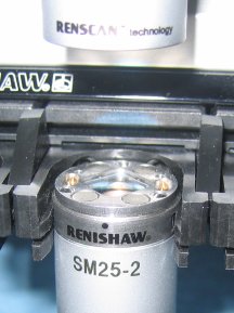
Slowly lowering the probe body:
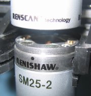
Module jumps upward for a good alignment:
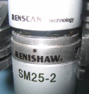
Module tilted for a poor alignment:
When you have established a good alignment, click OK. The following prompt appears:
Slowly lower the probe body onto the module. IMMEDIATELY stop when the LED on the probe head illuminates and then click OK.
When you click OK the machine will begin a small DCC movement to finish seating the probe body into the module.
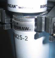
The image below shows the probe body that has been lowered just before the LED is lit:
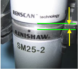
Notice the slight gap between the probe body and the SM25-2 module. From this point, continue to lower the probe body and stop when the LED is lit. This does not close the gap completely. To finish the process, click OK.
WARNING: When you do this, the machine moves. To avoid injury, stay clear of the machine. To avoid hardware damage, run the machine at a slower speed.
At this point, the probe body automatically moves down the rest of the way to seat the probe module and close the gap. The following prompt appears:
Moving in only the one axis (as much as possible) please move the probe clear from the port and then click OK.
Move the probe straight out from the port to a position in front of the port as shown in the following image:
Click OK. This completes the measurement of port 2. PC-DMIS then prompts you to set the configuration back to the original probe configuration:
Please restore the probe configuration for probe SP25_4_X_50 and then click OK.
If needed, remove the current module, and add the modules and tips that make up the requested probe file. When you are done, click OK. The following prompt appears:
This calibration procedure is now complete.
This step completes the calibration of the FCR25 Probe Changer. The next step describes how to review your calibration.