The 2D Radius Gage dialog box has these tabs:
Properties tab
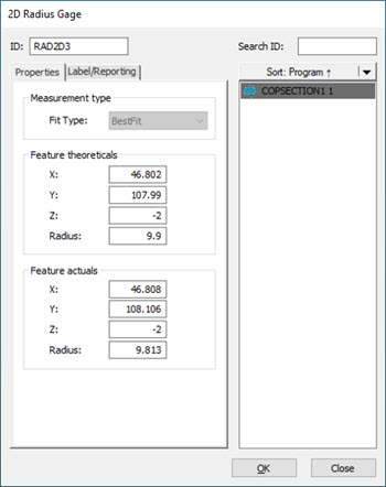
2D Radius Gage dialog box - Properties tab
The 2D Radius Gage is automatically linked to the cross section on which it was created. Since you created the 2D Radius Gage on the cross section, you cannot change the associated cross section.
The Properties tab of the 2D Radius Gage dialog box has these areas:
Measurement type
Fit Type - Click the drop-down arrow to display these options:
Best Fit - The software applies a Best Fit Least Square fit to all data points that fall within the radius search zone.
Feature theoreticals - The software displays the XYZ centerpoint location and size of the nominal radius. You can edit the nominal values.
Feature actuals - The software displays the XYZ centerpoint and size of the measured radius. You cannot edit the actuals.
Label/Reporting tab

2D Radius Gage dialog box - Label/Reporting tab
The Label/Reporting tab of the 2D Radius Gage dialog box has these areas:
Tolerances
The Dimension Color Scale defines the default 2D Radius Gage tolerances. For details, see "Editing Dimension Colors" in the PC-DMIS Core documentation.
The Tolerances section allows you to type the plus and minus tolerances for the radius.
To enter the plus, minus, and nominal tolerances, do the following:
Type the plus tolerance value in the Plus box.
Type the minus tolerance value in the Minus box.
If you are using a CAD model, the cross section nominal (black) polyline defines the nominal (theoretical) radius. If you are not using a CAD model, the software updates the nominal value with the initial measured value. You can edit the nominal value.
Label
Show check box - When you select this check box, the software displays the 2D Radius Gage label and graphic in the Graphic Display window.
Show heading check box - This check box toggles the display of the row and column headings in the 2D Radius Gage label. When you select this check box, the software displays the label's row and column headings.
Contents
The order in which you select the following check boxes defines the order in which they appear in the label. The order number appears to the left of each selected item. When you clear a check box, the software reorders the order numbers of the remaining selected check boxes accordingly.
Measured check box - When you select this check box, the software displays the measured data in the label.
Nominal check box - When you select this check box, the software displays the nominal data in the label.
Tolerances check box - When you select this check box, the software displays the tolerance data in the label.
Deviation check box - When you select this check box, the software displays the deviation data between the measured and nominal values in the label.
OutTol check box - When you select this check box, the software displays the out-of-tolerance data in the label.
Default button - Click to set the current selection of check boxes as the default.
Reset button - Click to clear all check box selections in the Contents area. The software then resets the section to the auto-setting configuration showing the measured value.
Report and statistics
From this section, you can use the options to control the output results:
STATS - When you select this option, the software sends the output to statistical files.
REPORT - When you select this option, the software sends the output to the inspection report.
BOTH - When you select this option, the software sends the output to the inspection report and the statistical files.
NONE - When you select this option, the software doesn’t send output anywhere.
When PC-DMIS executes the command, the software sends the results to the specified output.
If you choose STATS or BOTH, a preceding STATS/ON command must exist inside the Edit window in order to send the results to the statistical file.
More: