2D Radius Gage Overview
The 2D Radius Gage function is a quick-check tool that
you can use to measure the radii on a pointcloud or mesh cross section.
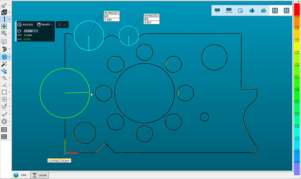
You can create a 2D Radius Gage graphically on a cross
section in the 2D Slide Show view.
To create a 2D Radius Gage graphically, do the following:
After you create the cross sections, from the
Mesh, Pointcloud,
or QuickCloud toolbar (View
| Toolbars), click the Cross Section Slide
Show button ( ) to display the cross
sections in 2D view. For details, see the "Cross
Section Slide Show" section of the "Show
and Hide Cross Section Polylines" topic.
) to display the cross
sections in 2D view. For details, see the "Cross
Section Slide Show" section of the "Show
and Hide Cross Section Polylines" topic.
Hold down the Shift key, and move the mouse
cursor onto the radius to view the nominal, measured, and deviation
values in the display widget.
Left-click to select the radius. You can create
or cancel the radius gage from the widget dialog box.
The software uses a Least Square Best Fit algorithm
to calculate the 2D Radius by default. The active tolerances are set on
the Dimensions Color Bar. The radius gage graphic uses the color from
the Dimensions Color Bar which corresponds to its deviation. For details
on editing the dimension color scale, see "Editing
Dimension Colors" in the PC-DMIS Core documentation.
You can change the tolerances for the gage from the
Edit window, or press the F9 key to view the 2D Radius
Gage dialog box.
Examples of the 2D Radius Gage
By default, PC-DMIS automatically includes the 2D Radius
Gage in the report.
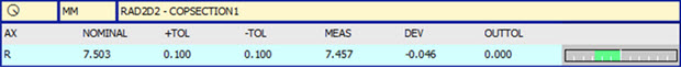
Example of a 2D Radius Gage report
You can turn off showing the 2D Radius Gage in the
report from the Label/Reporting tab of the 2D Radius Gage dialog box. For details, see "2D Radius Gage Dialog Box".
Once you create a 2D Radius Gage, you can use it in
Location and Distance Dimensions, and Constructions. For Location Dimension,
Form is not supported.
More:
2D
Radius Gage Dialog Box
Creating
a 2D Radius Gage
CROSS
SECTION
2D
View of Cross Sections