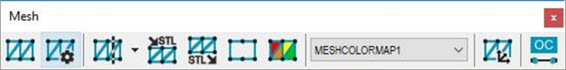
Mesh toolbar
The Mesh toolbar provides all mesh operations, features, and functions. It is accessible from the View | Toolbars | Mesh menu.
The Mesh license must be enabled to use or view this option.
The following options are available from this toolbar:

Mesh: Displays the Mesh Command dialog box used to create mesh features from any number of pointclouds. For details on this dialog box and creating mesh features, see the "Creating a Mesh Feature" topic.

Mesh Operator: Displays the Mesh Operator dialog box used to perform different operations on a Mesh and other Mesh operator commands. For details on the dialog box and creating mesh operators, see the "Creating a Mesh Operator" topic.

Mesh Cross Section: Displays the Mesh Operator dialog box to create a cross section from an existing mesh. Click the drop-down arrow to display the Mesh Cross Section toolbar:
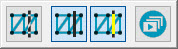
For details on Mesh cross sections and using the Mesh Cross Section toolbar, see "Mesh CROSS SECTION Operator" in this documentation.

Import Mesh in STL Format: Displays the Mesh Import Data dialog box used to import an STL mesh data file. If a Mesh object does not exist in the PC-DMIS Edit window, then a new Mesh object is created, and the STL data is imported. If a Mesh object already exists in the PC-DMIS Edit window, then the STL data is added to the Mesh object.
For details, see the "Mesh IMPORT Operator" topic.

Export Mesh in STL Format: Displays the Export Mesh Data dialog box used to export a Mesh in an STL ASCII or STL Bin file format.
For details, see the "Mesh EXPORT Operator" topic.
![]()
Empty a Mesh: Empties the first mesh relative to the cursor position in the Edit window.
Once this command has been applied to a Mesh, there is no way to restore Mesh data that was removed. Undo does not restore this data.
For details, see the "Mesh EMPTY Operator" topic.

Colormap a Mesh: This displays the Mesh Operator dialog box that you can use to create a Mesh COLORMAP operator. For details, see the "Mesh COLORMAP Operator" topic.
The Colormap a Mesh operation applies a colored shading to the selected mesh. The model is shaded according to the deviations of the mesh compared to the CAD. The Colormap a Mesh operation uses the colors defined in the Edit Dimension Color dialog box and the tolerance limits specified in the Upper tolerance and Lower tolerance boxes. For details on the Colormap a Mesh operator, see the "Mesh COLORMAP Operator" topic in the PC-DMIS Laser documentation.
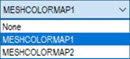
You can create multiple colormaps in a PC-DMIS measurement routine. However, only one is active. The last colormap that was applied and created (pointcloud surface colormap or mesh colormap), or the last one executed, is always the currently active colormap. You can also select which colormap is the active one from the Colormaps list box. When you activate a new colormap, PC-DMIS displays its associated scale with tolerance values and any annotations in the Graphic Display window.
To do this, click the Colormaps list box and select the colormap from the list of defined colormap operators:

Mesh Alignment: Displays the Mesh/CAD Alignment dialog box. It is used to create Mesh to CAD alignments.
For details, see the "Mesh ALIGNMENT" topic.

Receive
a mesh from OptoCat: When clicked ON, PC-DMIS is placed in a state
where it is waiting and ready to receive a mesh from the OptoCat application.
When the Receive a mesh from OptoCat button
is ON, it has a darker background color:  .
For details on how this works, see the "Receive
a Mesh from OptoCat" topic.
.
For details on how this works, see the "Receive
a Mesh from OptoCat" topic.
More: