
PC-DMIS allows you to manually scan the surface of your part into pointclouds. From pointclouds, you can then extract Auto Features for addition to your measurement routine. Portable laser probe scanning can be accomplished with a Perceptron or CMS laser probe, or you can use a Leica T-Probe scanner.
For information on setting up and using a Perceptron or CMS laser probe, see the "Getting Started" chapter of the PC-DMIS Laser documentation.
For information on setting up and using Leica T-Probe scanners, see "Using a Leica Laser Tracker" in this documentation.
Creating a Manual Scan
To begin scanning in Learn Mode, you should do the following:
[optional] Add a COP command to your measurement routine to which the scanned data will be added. To do this, select the Insert | Pointcloud Feature menu item, or click the Pointcloud button on the Pointcloud toolbar.
If you begin scanning without first creating a COP command, PC-DMIS automatically creates a COP for the scanned data.
Scan the surface of the feature or features. This may take more than one pass. The software displays the scanned stripes in the Graphic Display window in real-time. If you are using an existing COP, PC-DMIS prompts you to empty it.
Select Auto Features that reside within the pointcloud as described in the "Extracting Auto Features from Pointclouds" topic in the Laser documentation. When an Auto Feature is created, the pointcloud for the feature is extracted and appears on the Laser Scan Properties tab in the Laser Probe Toolbox.
Auto Zoom and Auto Rotate
When you use a portable arm or laser tracker to scan, PC-DMIS automatically rotates and zooms the pointcloud in real-time in the Graphic Display window to show the proper view.
This is done with the Auto Rotate check box and the Zoom options located on the Laser Scan Display Properties tab of the Probe Toolbox (View | Other Windows | Probe Toolbox).
Probe Toolbox - Laser Scan Display Properties tab with Auto Rotate and Auto Zoom options selected
PC-DMIS enables the Auto Rotate and the Auto option in the Zoom section by default.
Auto Rotate check box - If this check box is selected, the pointcloud automatically rotates in the Graphic Display window based on the laser line orientation. The rotation occurs even you are not scanning. This allows you to position the scan line on the part before triggering a scan pass. When disabled, no rotation occurs in the Graphic Display window while laser scanning.
Zoom section - You have three options:
None - This disables auto zoom. The software uses the last manual user-defined zoom setting to show the pointcloud scan in the Graphic Display window.
Auto - If this option is selected, the Graphic Display window zooms into a close-up view, centered in the middle of the laser scan line. As you scan more of the part, the Graphic Display window zooms out to show the collected pointcloud data.
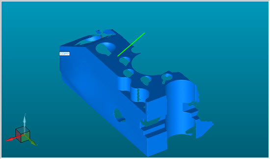
Graphic Display window showing the scan line with Auto Zoom option selected
Custom (%) - If this option is selected, you can set the zoom percentage. 100% indicates the zoom factor is set using the actual part size (1:1 relationship). You can set the zoom percentage larger to a get a close-up view of the scan or smaller to see more of the pointcloud at a reduced size. For example, 50% would be half size.

Probe Toolbox - Laser Scan Display Properties tab with Auto Rotate and Custom (%) Zoom options selected