Runout Feature Control Frame (FCF) dimensions are often used to determine the coaxiality of a selected feature with respect to a selected datum or datums. You must select at least one datum when you create a runout FCF dimension.
There are two types of runout:
Circular Runout - Checks just one level of hits, one circle, around a cylindrical feature.
Total Runout - Checks multiple levels of hits along the entire surface of the cylinder.
In addition, the Feature Control Frame tab in the XactMeasure GD&T dialog box (Insert | Dimension | <dimension>) contains two options buttons, Axial and Radial:
If the considered feature is a plane or set of planes, only the Axial option is permitted and PC-DMIS automatically grays out both buttons and selects Axial.
If the considered feature is an axial type feature, PC-DMIS selects Radial by default unless you define a single plane datum. In this case, PC-DMIS automatically selects Axial and grays out both buttons.
These buttons are discussed in the "Feature Control Frame Tab" topic under "Feature Control Frame Options" and then "Axial and Radial options".
Axial Runout
This type of runout is measured on the end surface of a cylindrical part. The end of the cylinder can be measured as a circle or a plane.
Circular
Axial Runout - PC-DMIS
looks at each circle section separately (this implies sets of circles
and sets of circle scans, not a plane or set of points). It computes
the axial runout tolerance for each circle section based on the minimum
spread of two parallel planes perpendicular to the datum axis, containing
all the points of that circle section. The reported circular
axial runout tolerance is the worst case of these individual circle
sections.
Available feature types for the considered feature are: scans,
circles, sets of scans, and sets of circles.
Total
Axial Runout - PC-DMIS
finds two parallel planes perpendicular to the datum axis, as close
together as possible while still containing all the measure points
(for all scans or circles taken together). The spread of these
two parallel planes is the total axial runout tolerance.
Available feature types for the considered feature are: scans,
circles, planes, sets of scans, and sets of circles.
Radial Runout
This type of runout is measured on the cylindrical surface of a bore or shaft.
Circular
Radial Runout - PC-DMIS
looks at each circle section separately (this implies sets of circles,
sets of circle scans, or a cylinder with multiple circle sections,
not a plane or set of points). It computes the radial runout tolerance
for each circle section based on the minimum spread of two concentric
circles centered on the datum axis, containing all the points of that
circle section. The spread of these two concentric circles is
the circular radial runout for that circle section. The reported circular
axial runout tolerance is the worst case of these individual circle
sections.
Available feature types for the considered feature are: scans,
circles, cylinders, cones, spheres, sets of scans, sets of circles,
sets of cylinders, sets of cones, and sets of spheres.
Total
Radial Runout - PC-DMIS
finds two concentric cylinders centered on the datum axis that are
as close together as possible while still containing all the measure
points (for all scans or circles or cylinders taken together). The
spread of these two concentric cylinders is the total radial runout
tolerance.
Available feature types for the considered feature are: scans,
circles, cylinders, cones, spheres, sets of scans, sets of circles,
sets of cylinders, sets of cones, and sets of spheres.
Single Datums
Both circular and total runout (axial and radial) require at least one datum.
If only one datum is specified and the runout type is Radial, then the datum must be an axial type feature (cylinder, cone, line).
If only one datum type is specified and the runout type is Axial, then the datum may be an axial type feature or a plane.
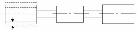
Two Datums
If the runout type is Radial, then you may specify two datums.
The primary datum is generally a plane that lies nominally perpendicular to the axis of the considered feature (which in this case would be an axial type feature).
The secondary datum would be an axial type feature.
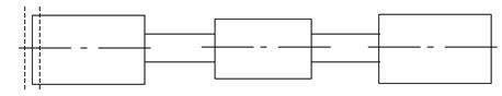
Compound Datums
The datum may also be a compound datum that references two cylinders (such as A-B). If the runout type is Radial, then you may specify two datums.
The primary datum is generally a plane that lies nominally perpendicular to the axis of the considered feature (which in this case would be an axial type feature).
The secondary datum would be an axial type feature.