
GD&T dialog box - Feature Control Frame tab
The Feature Control Frame tab in the XactMeasure GD&T dialog box (Insert | Dimension | <dimension>) helps you construct a Feature Control Frame (FCF). It provides you with tools that you can use to define datum features, select the features used in the FCF dimension, and define the specific symbols, tolerances, and datums used in your FCF. It also provides a preview area that displays the current state of the FCF as you build it. For information on the items on this tab, see the list of controls below:
ID - This box displays the name for the FCF. You can edit it if you want something different.
Feature - This list lets you choose the considered features for a particular FCF type. Some features may exist in the measurement routine but are not available to the FCF. For example, a plane feature is not available to Circularity. PC-DMIS updates this list after you select the first feature. This ensures that when you create a pattern of features for the FCF, those features are compatible features.
 Reorder Selected Items - This button shows a Selected Items list with all the selected items.
When you select items, a small number appears next to that item in the
Feature list. These numbers indicate the order
of selection. The Selected Items list contains
small up-and-down black arrows next to each item that let you rearrange
the selection order of the selected items. A small x next to each item
lets you deselect items from the list of selected items.
Reorder Selected Items - This button shows a Selected Items list with all the selected items.
When you select items, a small number appears next to that item in the
Feature list. These numbers indicate the order
of selection. The Selected Items list contains
small up-and-down black arrows next to each item that let you rearrange
the selection order of the selected items. A small x next to each item
lets you deselect items from the list of selected items.
 Clear
Selection - This button clears all the selected items in the Feature list. The number in parentheses to the
left of this button indicates the number of selected items.
Clear
Selection - This button clears all the selected items in the Feature list. The number in parentheses to the
left of this button indicates the number of selected items.
 Select All - This button selects all the features
in the Feature list.
Select All - This button selects all the features
in the Feature list.
Feature Control Frame Editor - This editor is below the ID and GD&T Standard items. You can use this area to apply changes to the FCF.
The FCF Editor
If a plus button ( )
appears to the right of the FCF, you can use it to access the Datum
Definitions dialog box, which enables you to define datums for
your current FCF dimension.
)
appears to the right of the FCF, you can use it to access the Datum
Definitions dialog box, which enables you to define datums for
your current FCF dimension.
You can select fields with your mouse pointer or by pressing Tab and then Enter to place the field into edit mode. If the field is editable, it displays either a list of available options or a box into which you can type text. When you finish editing a field, press the Enter or Tab key, or click on a different field to exit edit mode. To move backwards to the previous field, press Shift + Tab.
When a field is empty, a short description displays with brackets around it for identification. These descriptions correspond to these fields:
<UA> - Unit Area (Only for Flatness FCF dimensions. See the "Per Unit Check Box" topic below.)
<UZ> - Unequal tolerance zone (only for Profile FCF dimensions)
<UTol> - Unequal tolerance value (only for Profile FCF dimensions)
<MC> - Material condition
<size> - Material boundary size
<D> - Diameter
<Dim> - Dimension or feature control frame type
<PZ> - Projected zone
<num> - Number of features
<nom> - Nominal of feature size
<+tol> - Plus tolerance
<-tol> - Minus tolerance
<tol> - Tolerance
<dat> - Datum
<sym> - Dimension symbol
[x,y,z or u,v,w] - Customized datum reference frames. See "Creating a Customized Datum Reference Frame".
<add notes here> - Note field in the first line
<add optional design notes> - Optional design notes in the last line
Spherical Zone - You can
use a spherical tolerance zone if you have a Position FCF for a point
or sphere feature. To enable a spherical tolerance zone, select the feature
to dimension. Then, in the FCF editor, select the diameter symbol  and change it to the
spherical zone symbol as shown here:
and change it to the
spherical zone symbol as shown here:

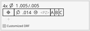
Planar Zone - This button
appears in the Feature Control Frame Editor
area of this tab if you are defining a Position FCF dimension or one of
the orientation FCF dimensions (Perpendicularity, Parallelism, or Angularity),
and the tolerance zone is set to a planar zone. To enable a planar zone
and display the Planar Zone button, select the
diameter symbol
from the FCF editor and set it to blank as shown here:

Once the Planar Zone button appears, you can click it to open the Planar Zone Direction dialog box:
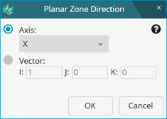
Planar Zone Direction dialog box
PC-DMIS selects the direction vector by default when the considered feature is a plane or line. For non-planar features (circles, cylinders, and spheres), you must specify the planar zone direction by selecting either axes or vector and type the nominal IJK values.
The Planar Zone Direction dialog box lets you specify the direction vector for the planar zone in one of two ways:
Choose an axis in the current active alignment.
Select the Axis option. Then from the
Axis list, select an axis: X,
Y, Z,  Radial
Arc, or Right Angle to Radial.
Radial
Arc, or Right Angle to Radial.
Input the IJK of the direction vector directly. Select the Vector option. Then in the I, J, and K boxes, type the direction vector.
This direction vector is applied to the current active alignment.
Feature Control Frame Options - The options in this area change based on the type of FCF dimension you are creating.
Actions and Procedures - This section displays hints and instructions to assist you in building valid FCFs.
Preview
- This section displays a preview of the FCF with the current settings.
It does not include any of the empty fields or empty descriptions that
appear in the Feature Control Frame Editor section,
such as fields that have brackets; for example:
"<dat>".
Notes on the Feature Control Frame Editor
Be aware that some of the icon fields in the Feature Control Frame Editor area do not appear for certain dimensions if they are not supported. For example, if you have a Circularity dimension, PC-DMIS displays the tolerance field but hides any datum or modifier fields.
Form dimensions (Circularity or Roundness, Cylindricity, Flatness, Profile with Form Only) - These don't support datums or modifiers, so these fields do not appear. Profile in some cases falls in this category when checking for "Form Only". But "Form and Location" for Profile dimensions allows the display of modifiers.
Orientation dimensions (Parallelism, Perpendicularity, Angularity) - These allow datums and modifiers.
Location dimensions (Position, Concentricity, Coaxiality, Symmetry, Profile with Form and Location) - These allow datums and modifiers.
Runout dimensions - These must have datums.
Straightness dimension - This dimension supports modifiers if the feature being dimensioned for straightness is a cylinder feature. It does not support datums.
Also, only these dimensions can have multiple lines in the editor:
Position
Parallelism
Perpendicularity
Tolerance Zones for Form Dimensions
For information on how PC-DMIS reports tolerance zones for form dimensions, see "Reported Tolerance Zones for Form Dimensions" in the "Reporting Measurement Results" chapter.


