A stand-alone Fixturing System Setup application is
included with PC-DMIS. It can help you set up your Flexible Fixturing
system. After you install PC-DMIS, you need to run the Setup utility.
The information in this topic provides an overview
of the steps that you need to take to set up and run Fixturing.
You must be logged into Windows as an administrator in
order to use the FxtServerInterface application to set up the machine
and its connection. If you are logged into Windows under a standard user
account without administrator privileges, the application will run, but
you will not have access to any machine or connection setup functionalities.
First-Time PC-DMIS Installation with Fixturing
To be compliant with the permission rules for PC-DMIS
products, files associated with Fixturing are located in this folder:
This folder allows access to the files without needing
administrator privilege on the computer that is running PC-DMIS.
To do this, you must perform the following steps when
you install PC-DMIS for the first time:
The first time you install PC-DMIS and FXtServer,
run the FXtServer installation program for the first time with administrator
privileges (as is required for the PC-DMIS installation).
When you run FxtServerInterface, a message
appears and states that the system will migrate all of your data files
to the FIVEUNIQUE folder in the path above.
If you select Yes,
the files are moved, and the original
folder is deleted.
If you select No,
the files are copied, but the original
folder is retained.
Once this is done, the files are moved (or copied),
and you are able to run FxtServerInterface.exe without administrator privileges.
Step 1: Run the Fixturing System Setup Utility
From your PC-DMIS installation directory, open the
FiveUnique subdirectory, and double-click on fxtserverinterface.exe
to open a small Fixturing System Setup window. (Or, if a shortcut exists,
you can select Start | All Programs | PC-DMIS (version)
| Fixture Interface Server.)
Step 2: Connect to a Fixture Server
From the Fixturing System Setup window, select
Configuration | Connection to open the Properties dialog box. This dialog box defines
the connection properties and settings to the fixture server. For
more information, see "Fixture
Server Connection".
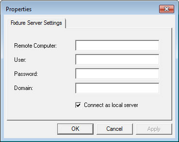
Properties dialog box - fixture server settings
tab
Complete the dialog box:
Remote
Computer - To connect to a remote server, type the name
of the remote computer. To connect to a server running on your
computer, type localhost.
User
- Type a user name with administrator access.
Password
- Type the password the user uses to log in.
Domain
- If needed, specify the domain name.
Connect
as local server - If you're connecting to a server running
on your local computer, mark this check box. If you're connecting
to a remote server, leave it blank.
Click OK to connect
to the server with the specified login credentials.
Step 3: Select the Fixture System
From the Fixturing System Setup application,
select File | Set System to open the Select System dialog box. You can use this dialog
box to define the type of fixture system to use.
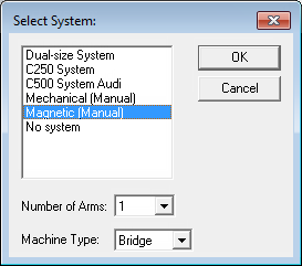
Select System dialog box
From the list box, select the correct system
from the available systems.
For Number of Arms,
select the number of arms used on your setup.
For Machine Type,
select your machine type:
For CMMs with
measuring arms in a vertical position, select Bridge.
For CMMs with
measuring arms in a horizontal position, select Horizontal.
Click OK
to close the dialog box. The Fixturing System Setup window reflects
your changes.
Step 4: Define the Fixture Properties
From the Fixturing System Setup window, click
Properties to open the Fixture
Properties dialog box.
From the Fixture Properties
dialog box, configure the properties for the following items:
Once you have defined and positioned the fixtures in
PC-DMIS, you need to calibrate them so that PC-DMIS knows where the fixtures
are in relation to the coordinate system.
Select the Operation | Calibrate/Edit
| Fixturing menu option to open the Calibrate
Columns tab in the Fixturing Setup
dialog box.