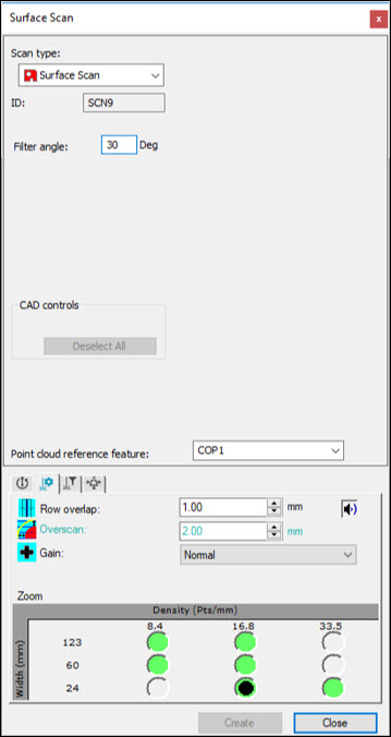
Surface Scan dialog box
The Surface Scan dialog box creates a series of scans to cover a selection of surfaces. For example:
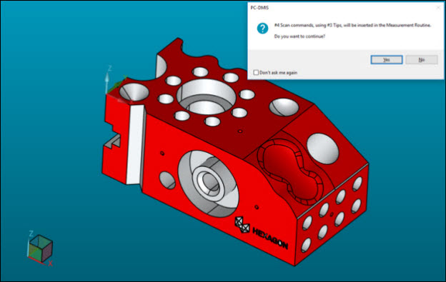
Example of a Surface Advanced scan
Creating a Surface Advanced Scan
Ensure that you have a Laser probe enabled.
Place PC-DMIS into DCC mode.
Verify that the CAD vectors on the surfaces are correctly defined. If necessary, you can adjust them in the CAD Vectors dialog box (Edit | Graphic Display Window | CAD Vectors). For more information, see the "Editing CAD Vectors" topic in the "Editing the CAD Display" chapter in the PC-DMIS Core documentation.
Create a COP in the Pointcloud dialog box (Insert | Pointcloud | Feature). For details on pointcloud features and how to create a COP, see the "Using Pointclouds" chapter.
Set the appropriate scan speed. For details, see the "Getting Started" chapter.
Select the Insert | Scan | Surface Scan menu item. The Scan dialog box appears with the Surface Scan already selected in the Scan type list.
In the Filter Angle box, type the appropriate filter angle.
In the Point cloud reference feature list, select the pointcloud reference feature.
Open the Probe Toolbox (View | Probe Toolbox). Do the following:
On the Laser Scan Properties tab, select the appropriate scan settings.
On the Laser Filtering Properties tab, select the appropriate filter settings for the scan.
On the Laser Clipping Region Properties tab, select the appropriate clipping parameters for the scan.
In the Graphic Display window (View | Graphic Display Window), select the surfaces on the CAD that the surface scan should cover. For help, see the "Editing the CAD Display" chapter in the PC-DMIS Core documentation.
Click the Create button. PC-DMIS inserts the necessary scans into the Edit window. For example:
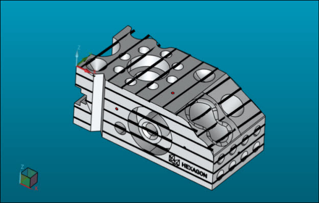
Example of a Surface Advanced scan in the Edit window
Note the following:
The surface scan is a one-time operation to create a list of scans.
You cannot edit these scans.
A verification if the scans can execute collision-free is necessary.
A full coverage on the selected surfaces depends on their complexity. Full coverage is detectable if you execute the scans offline.
The computation time for the scans depends on the complexity of the selected surfaces.