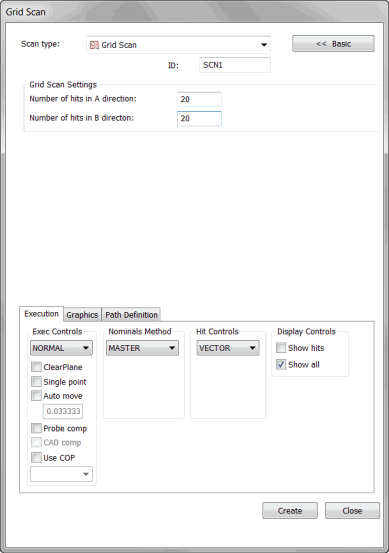

Grid Scan dialog box
The Grid scan, similar to the UV scan, enables you create a grid of points within a visible rectangle and then project those points down on top of any selected surfaces. UV and Grid scans are similar in the way they construct and space points within a selected area. However, UV scans use the UV space as defined by the CAD model. You can use the Grid scan to create a grid in the current CAD orientation and project the points onto the CAD surface.
Consider these two figures:

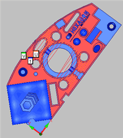
Figure 1 - UV Scan on 2D Rotated Part

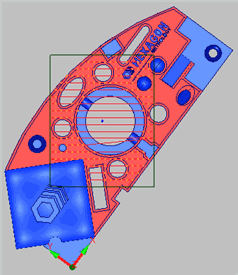
Figure 2 - Grid Scan on 2D Rotated Part
Figure 1 shows a UV scan on the top surface of a 2D rotated sample block. Figure 2 shows the same block with a Grid scan. Notice how the UV axes in figure 1 are in line with the XY axes of the selected surface. The Grid scan, on the other hand, does not do this; instead, the points remain aligned with the rectangle view. When created, the Grid scan creates the points where they fall on the selected surfaces, regardless of the part orientation.
To Create a Grid Scan
Enable a TTP probe.
Place your CAD model in Solid mode.
Place PC-DMIS in DCC mode.
Access the Grid Scan dialog box (Insert | Scan | Grid).
Type the name of the scan in the ID box if you want to use a custom name.
Click and drag a  rectangle
on the screen over the surface or surfaces you want to include in
your scan. This rectangle defines the boundary of the grid, which
will be projected onto the CAD surface(s).
On the Graphics tab, select the Select check box.
Click the surface or surfaces you will scan.
PC-DMIS highlights the  selected
surfaces as you select them.
Select the appropriate type of hits to take from the Hit Type list in the Hit Controls area. You can select either Vector or Surface.
In the Grid Scan Settings area, define how many hits in the A and B directions will get spaced and dropped onto the selected surface(s).
Modify any other options as needed. Only MASTER can be selected from the Nominals list.
Select the Generate
button in the Theoretical Path
area on the Path Definitions
tab to generate a preview of the scan on the CAD model in the
Graphic Display window. PC-DMIS will  draw
points on the CAD model. It will not draw points
on any surface you did not select, even if the boundary of the rectangle
includes other surfaces.
If needed, you can delete individual points. To do this, select them one at a time from the Theoretical Path area and press the Delete key.
If needed, make any modifications to your scan.
Click the Create button. PC-DMIS inserts the scan into the Edit window and draws the route the probe will take on the surface of the model in the Graphic Display window.