Select Edit | Preferences | Parameters to open the Parameter Settings dialog box.
Click the Clearance Plane tab.
In the Active plane area, set the following items:
Axis to ZPLUS
Value to 7
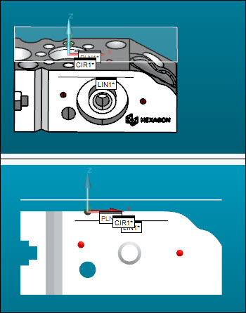
Select the Clearance planes active (ON) check box to automatically insert a MOVE/CLEARPLANE command between features you later measure in this tutorial.
Click Apply and then OK to close the dialog box. This also inserts a CLEARP command in the Edit window to define the clearance plane.
From the Graphic Items
toolbar, click the Show Clearance Plane
icon ( ) to show the clearance plane as a translucent
image. Your clearance plane should look something like this:
