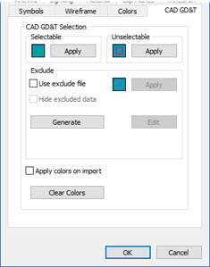
From the Edit menu, point to Graphic Display Window, and choose CAD GD&T to open the CAD GD&T tab.

CAD and Graphic Setup dialog box - CAD GD&T tab
The CAD GD&T tab of the CAD and Graphic Setup dialog box configures how CAD GD&T callouts appear in the Graphic Display window.
A CAD model with embedded CAD GD&T callouts typically has all of the dimensional requirements on it. However, some dimensional requirements you cannot measure (or should not measure) on a CMM.
This tab can help you indicate which dimensional requirements you want to include in the measurement routine when someone imports the CAD GD&T callouts as PC-DMIS features and dimensions and other commands. For information on how to work with GD&T callouts, see "Working with CAD GD&T Callouts".
The CAD GD&T tab consists of these areas and options:
CAD GD&T Selection area
These options configure the colors the software uses for CAD GD&T callouts in their different states.
Selectable - This option defines the selectable color. These are CAD GD&T callouts that are valid for GD&T selection.
Unselectable - This option defines the color for items that you cannot select. These are CAD GD&T callouts that are automatically invalid for GD&T selection. These include notes, surface finish, material specifications, and so forth.
Exclude area
You can use this area to manually exclude items from GD&T callouts that you could normally select. If you choose to exclude items, the lower part of this area lists the items that you have excluded. Excluded items are items that you have specifically identified as not wanted in the measurement routine. During CAD GD&T selection operations, PC-DMIS excludes those items.
This area also defines an optional exclude color for manually excluded items. You also have the option to hide excluded items entirely.
This area contains the following options:
Use exclude file - This check box tells PC-DMIS to use a .exclude file and exclude items you disabled from selection during CAD GD&T selection operations. These items take on the exclude color when you click Apply. The software lists the excluded items in the lower part of the Exclude area.
The exclude file must remain in the same directory as the measurement routine.
The exclude file's name must have the same name as the measurement routine. For example, if your measurement routine has the name of Circles.prg, the exclude file must have the name of Circles.exclude.
Color box - This opens the standard Color dialog box, so you can define the color for excluded items.
Hide excluded data - This check box hides any excluded items.
Generate - This button generates an exclude file from the CAD model. This text file contains all the embedded CAD GD&T callouts in the model. It has a filename of <measurement routine>.exclude, where <measurement routine> is the name of your current measurement routine. PC-DMIS stores this file in the same directory as your measurement routine.
By default, all the lines in this text file are enabled for selection by a single quote character at the beginning.
A sample line might look something like this:
' "24", Diameter Dimension 'PMILW_DIM_hole(24)', Characteristic ID: 24, Source seq: 2685, Sequence: 907
To make a line excluded from CAD GD&T selection, remove the beginning quote character.
Edit - This button opens the .exclude file inside of Notepad.
Apply Colors on Import - This check box is for convenience. It tells PC-DMIS to apply the selectable and unselectable colors defined here to the CAD model during import. The colors are applied automatically to the CAD GD&T objects at that time. Also, if you mark the Use exclude file check box above, PC-DMIS applies the exclude color to the imported model as well.
Clear Colors - This button resets all colors to their default values.
For information on how to work with the Color dialog box, see the "To Change a Color" topic.